Two-terminal switching devices and their methods of fabrication

a switching device and two-terminal technology, applied in the direction of semiconductor devices, solid-state devices, electrical devices, etc., can solve the problems of tfd fabrication process typically requiring less precision patterning, tfd fabrication consumes fewer resources than tft fabrication, and the tfd fabrication process typically requires less precision patterning. , to achieve the effect of high work function or fermi energy, good device performance, and high forward curren

Inactive Publication Date: 2013-05-16
FANTASY SHINE LTD +1
View PDF2 Cites 7 Cited by
  • Summary
  • Abstract
  • Description
  • Claims
  • Application Information

AI Technical Summary

Benefits of technology

[0016]The second conductive material is typically selected to have a relatively high work function or Fermi energy, e.g., at least about 4.8 eV, more preferably at least about 5 eV, and to be doped to a level producing a p+ or p++ type conductive material. The carrier concentration in the second conductive material should preferably be at least about 1018 cm−3, more preferably at least about 1019 cm−3. In some embodiments the materials are selected such that the energy barrier between the lowest energy level of the conduction band of the broad-band semiconductor material and the lowest energy level of the conduction band of the p+ or p++ type conductor material of the anode is less than about 0.3 eV. Such energy alignment maximizes the forward current in the device. However, if carrier concentration in the p++ material is sufficiently high (e.g., at least about 1019 cm−3), good device performance can be obtained even with significantly higher energy gaps than 0.3 eV.

Problems solved by technology

First, fabrication of TFDs consumes fewer resources than TFT fabrication.
Hence, expensive precise patterning is essential in TFT fabrication.
Since the diode current is determined by the overlaid area of the two contact electrodes, and this area is insensitive to shifts in the position of contact stripes, the TFD fabrication process typically requires less precision patterning.
In many cases, this requirement does not allow polymeric substrates with low melting point to be used for TFT-containing backplanes of displays.

Method used


Image

  • Two-terminal switching devices and their methods of fabrication
  • Two-terminal switching devices and their methods of fabrication
  • Two-terminal switching devices and their methods of fabrication

Examples


examples

[0110]Several examples of device compositions are herein illustrated in a cathode / semiconductor layer / anode format:

[0111]Ta / Ta2O5-δ / PEDOT:PSS;

[0112]Mg / Ta2O5-δ / PEDOT:Ag;

[0113]Ta / Ta2O5-δ / MEH-PPV / PEDOT:PSS;

[0114]Mg / Ta2O5-δ / ZnxCuyAlzSw;

[0115]ZnO / Ta2O5-δ / PEDOT:PSS.

[0116]Other devices can be configured using a variety of material combinations, e.g., using materials presented in Table 1 and Table 2.

TABLE 1Electronic properties of materials suitable for atwo-terminal device with an organic anode.Semi-AnodeconductorPEDOT:PSSPANI:IPPYPTT:NAFION ®Cath-Ec / Ev;Δ3 (eV)Δ3 (eV)Δ3 (eV)Δ3 (eV)odeΔ1 (eV)Δ4 (eV)Δ4 (eV)Δ4 (eV)Δ4 (eV)TaTaxOy0.00.40.7−0.53.9 / 7.9; ~0.31.31.10.81.7TiTixOy0.30.71.0−0.14.3 / 7.4; ~0.11.00.80.81.3ZnZnxOy0.30.71.0−0.14.3 / 7.3; ~0.11.00.80.51.3InInxOy0.20.60.9−0.34.1 / 7.6; ~0.11.10.90.61.5ZnZnxSy0.20.60.9−0.34.1 / 7.6; ~0.21.10.90.61.5

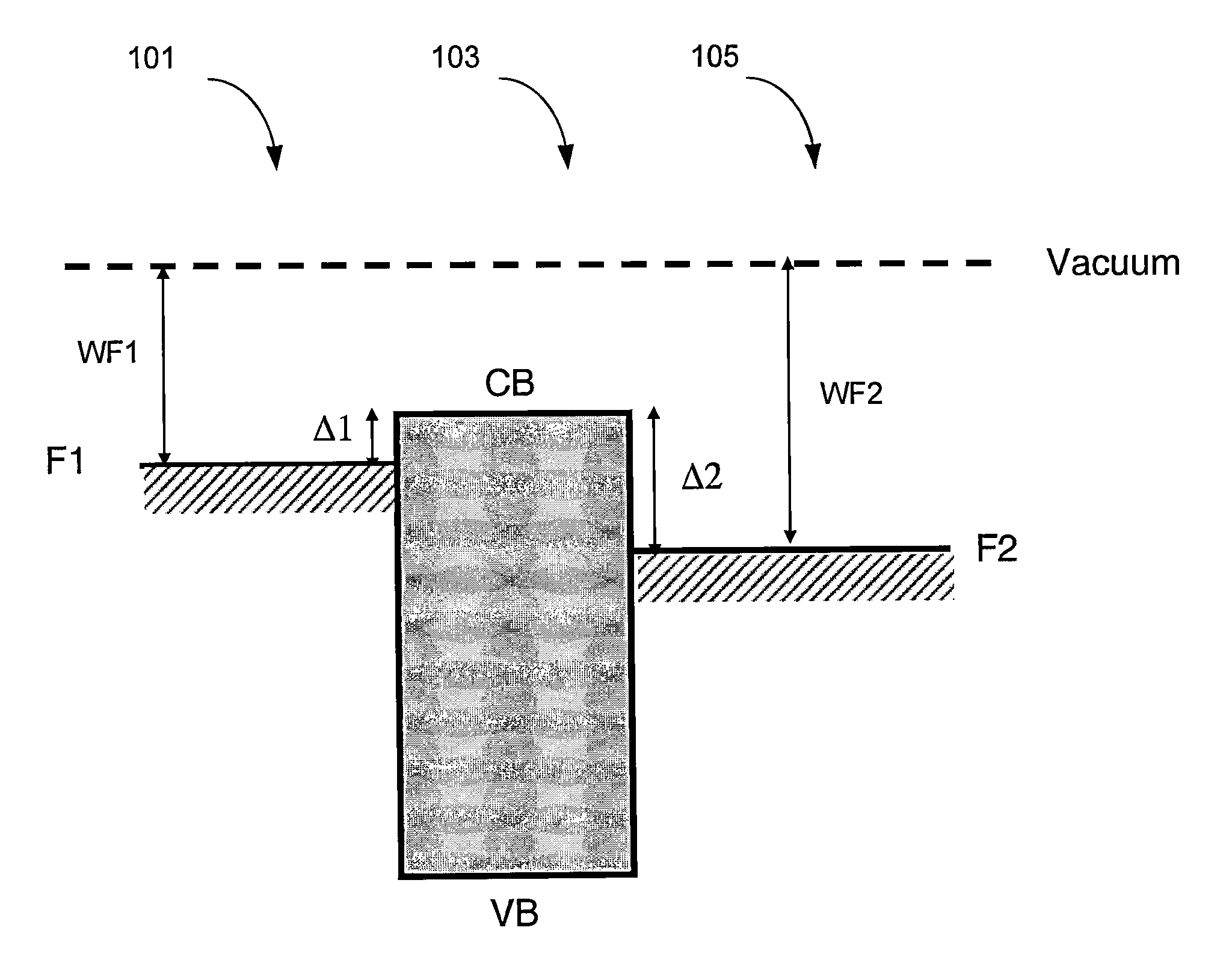
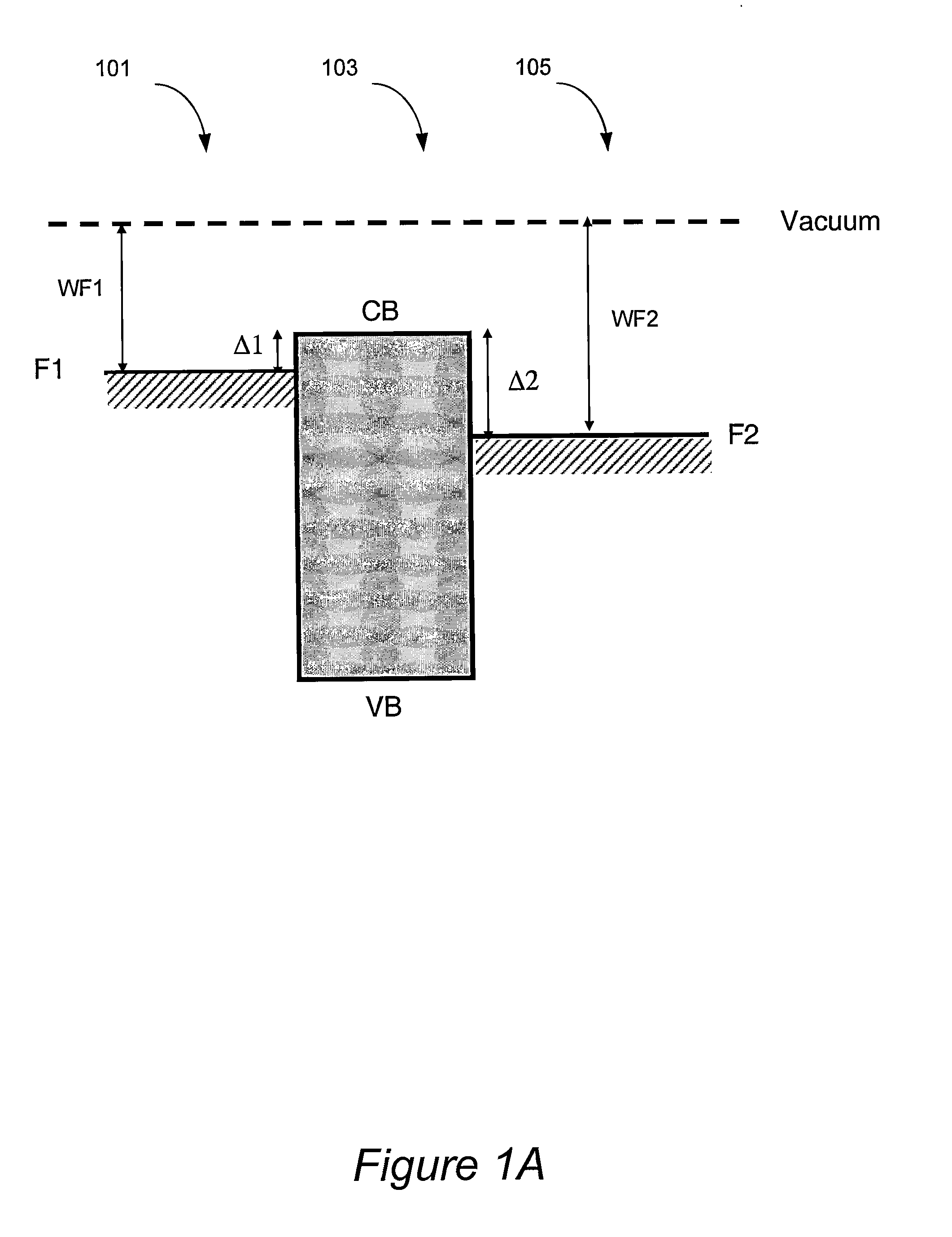
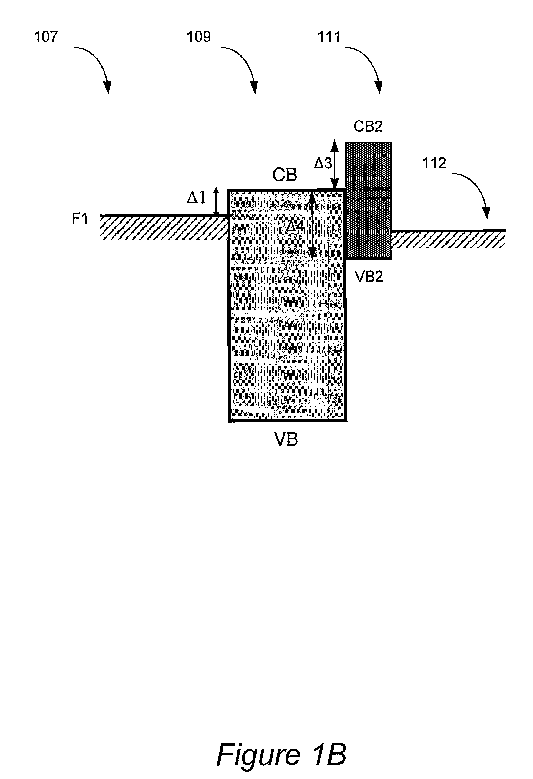
[0117]Table 1 illustrates several combinations of materials that can be used in two-terminal switching devices in accordance with electronic guidelines p...

experimental examples

[0119]A number of two-terminal switching devices have been prepared. Experimental methods used in device fabrication will now be illustrated. Methods used for determining electronic properties of various device materials will also be presented.

example 1

Organic p++ Materials Suitable for Anode Fabrication

[0120]Carrier concentrations were measured for several p++ materials. One example material for which carrier concentrations were determined was PEDOT:PSS, which was purchased from H.C. Starck Chemical (available as BAYTRON P®)). The electronic properties of aqueous colloid suspensions of PEDOT having different levels of PSS doping were determined. PEDOT / PSS ratios ranged from between 1:1 to 1:20. Table 3 lists materials used in this study, conductivity of these materials and their carrier densities. It can be seen that conductivity of these materials ranged from about 10−2 S / cm to about 6×10² S / cm.

TABLE 3Electronic parameters of PEDOT:PSSConductivityCarrier densityIDPEDOT:PSS(S / cm)(cm−3)1BAYTRON P PH500 ®~300~4 × 10212BAYTRON P PH ® ~0.3~3 × 10183BAYTRON Al 4083 ® ~10−2~1 × 10184BAYTRON P PH ® + 5% DMSO20-501-3 × 10²⁰ 

[0121]In one example, 100 nm thick PEDOT:PSS (product ID: BAYTRON P PH500®) films were spin-cast onto glass substra...


PUM

PropertyMeasurementUnit
carrier concentrationaaaaaaaaaa
band gapaaaaaaaaaa
decomposition pointaaaaaaaaaa

Abstract

Two-terminal switching devices characterized by high on/off current ratios and by high breakdown voltage are provided. These devices can be employed as switches in the driving circuits of active matrix displays, e.g., in electrophoretic, rotating element and liquid crystal displays. The switching devices include two electrodes, and a layer of a broad band semiconducting material residing between the electrodes. According to one example, the cathode comprises a metal having a low work function, the anode comprises an organic material having a p+ or p++ type of conductivity, and the broad band semiconductor comprises a metal oxide. The work function difference between the cathode and the anode material is preferably at least about 0.6 eV. The on/off current ratios of at least 10,000 over a voltage range of about 15 V can be achieved. The devices can be formed, if desired, on flexible polymeric substrates having low melting points.

Description

CROSS-REFERENCE TO RELATED APPLICATIONS[0001]This application is a continuation of U.S. patent application Ser. No. 13 / 015,013, filed Jan. 27, 2011, naming Yu et al. as inventors, which is a continuation of U.S. patent application Ser. No. 11 / 801,735, filed May 9, 2007, (now U.S. Pat. No. 7,898,042), naming Yu et al. as inventors, which claims benefit of prior U.S. Provisional Application No. 60 / 857,750 filed Nov. 7, 2006, titled “Metal-insulator-metal (MIM) devices and their methods of fabrication” naming Gong et al. as inventors, which are herein incorporated by reference for all purposes. This application is also a continuation-in-part of U.S. patent application Ser. No. 11 / 983,205, filed Nov. 6, 2007, naming Gong et al. as inventors, which is herein incorporated by reference for all purposes. This application is related to the following US patent applications, each of which is incorporated herein by reference in its entirety and for all purposes: (1) U.S. Provisional Application...

Claims


Application Information

Patent Timeline
Patent Type & Authority Applications(United States)
IPC IPC(8): H01L29/861
CPCH01L29/861H01L51/0587H01L51/004H01L45/00H10N70/00H10K85/141H10K10/29
Inventor YU, GANGSHIEH, CHAN-LONGLEE, HSING-CHUNG
Owner FANTASY SHINE LTD
Why Eureka
Try Eureka