Methods, Systems, Apparatuses, Circuits and Associated Computer Executable Code for Detecting Motion, Position and/or Orientation of Objects Within a Defined Spatial Region

a computer executable and spatial region technology, applied in the field of electronic devices, can solve the problems of affecting the appearance, the ability of few people to sense the hardness of touching, and the risk of damage by sharp objects, so as to improve the appearance, the effect of affecting the size and shap

Active Publication Date: 2013-05-16
EXTREME REALITY
View PDF15 Cites 80 Cited by
  • Summary
  • Abstract
  • Description
  • Claims
  • Application Information

AI Technical Summary

Benefits of technology

[0034]According to further embodiments, a controller of a display functionally associated with the active space may be adapted to alter the size, shape, appearance and / or location of elements within the display and / or alter the content and / or characteristics of the display based on the determined position, orientation and / or movement of objects within the active space. For example, a given icon upon an interactive display may be enlarged when it is determined that a finger of a user is approaching the given icon or the entire display may brighten when a finger approaches it.

Problems solved by technology

An early attempt at a handheld game console with touchscreen controls was Sega's intended successor to the Game Gear, though the device was ultimately shelved and never released due to the expensive cost of touchscreen technology in the early 1990s.
Until recently, most consumer touchscreens could only sense one point of contact at a time, and few have had the capability to sense how hard one is touching.
Disadvantages include the need to press down, and a risk of damage by sharp objects.
Resistive touchscreens also suffer from poorer contrast, due to having additional reflections from the extra layer of material placed over the screen
Surface wave touchscreen panels can be damaged by outside elements.
Contaminants on the surface can also interfere with the functionality of the touchscreen.
As the human body is also an electrical conductor, touching the surface of the screen results in a distortion of the screen's electrostatic field, measurable as a change in capacitance.
Unlike a resistive touchscreen, one cannot use a capacitive touchscreen through most types of electrically insulating material, such as gloves.
This disadvantage especially affects usability in consumer electronics, such as touch tablet PCs and capacitive smartphones in cold weather.
As it has no moving parts, it is moderately durable but has limited resolution, is prone to false signals from parasitic capacitive coupling, and needs calibration during manufacture.
However, moisture on the surface of the panel, high humidity, or collected dust can interfere with the performance of a PCT system.
This method produces a stronger signal than mutual capacitance, but it is unable to resolve accurately more than one finger, which results in “ghosting”, or misplaced location sensing
Infrared touchscreens are sensitive to dirt / dust that can interfere with the IR beams, and suffer from parallax in curved surfaces and accidental press when the user hovers his / her finger over the screen while searching for the item to be selected
When the sheet is touched by the user the deformation results in leakage of infrared light, which peaks at the points of maximum pressure indicating the user's touch location.
The technology claims to be unaffected by dust and other outside elements, including scratches.
A downside is that after the initial touch the system cannot detect a motionless finger.
First, each of these techniques requires specialized hardware.
This both raises the cost of implementing these techniques and prevents the use of these techniques with existing systems (i.e. there is no possibility of integrating these methods into existing displays).
Furthermore, all of these techniques require the user to actually touch the screen.
This limits the possible designs and implementations of such products and further negates the possibility of separating the display from the interacting area / surface.

Method used

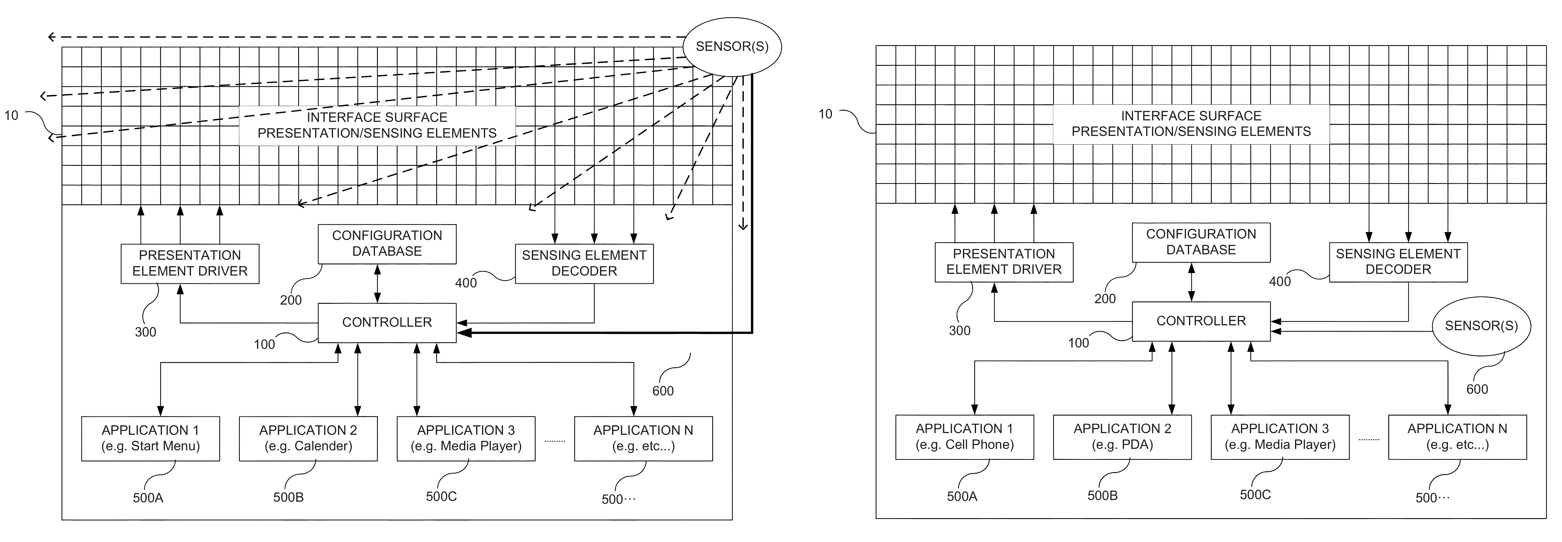
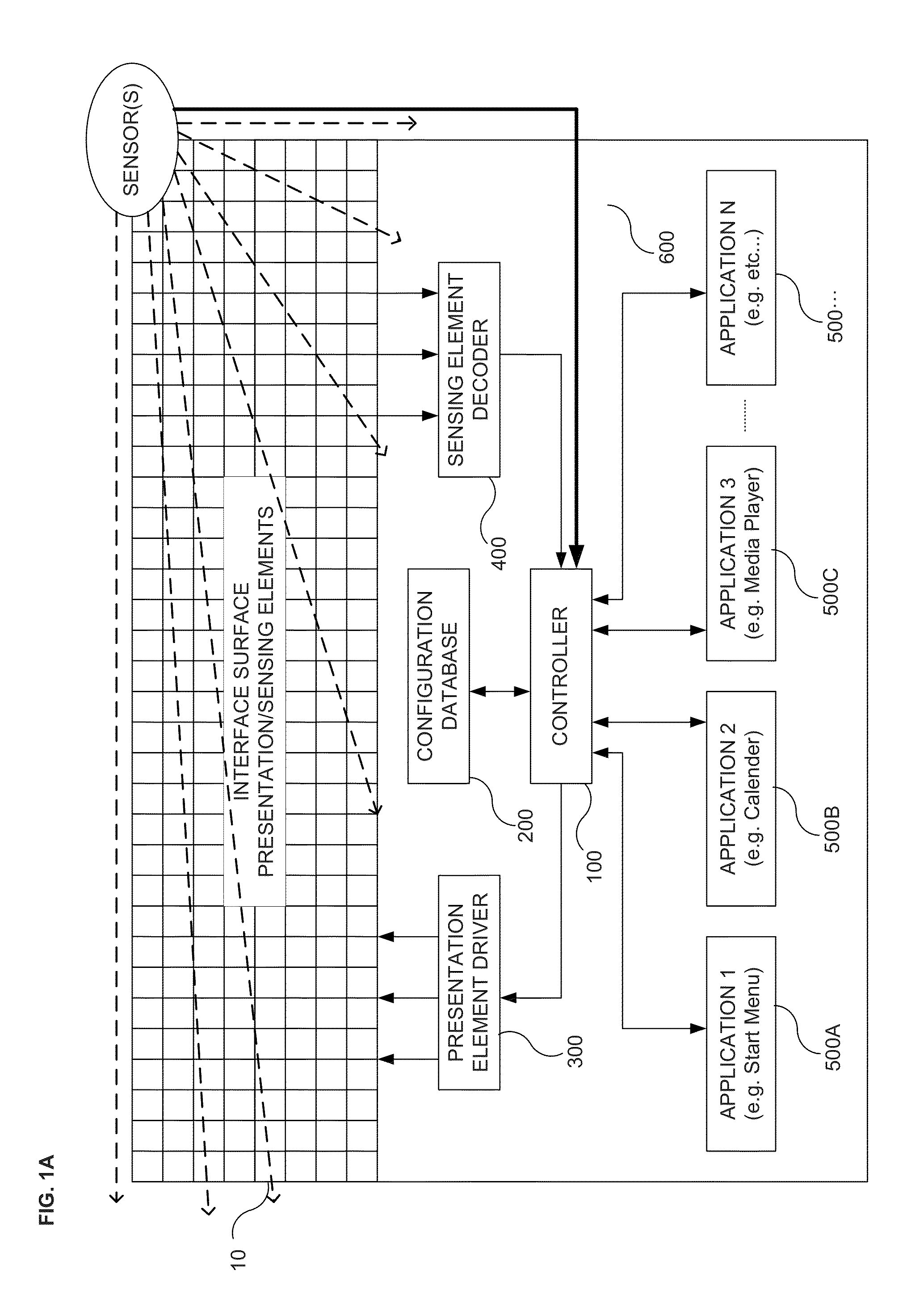
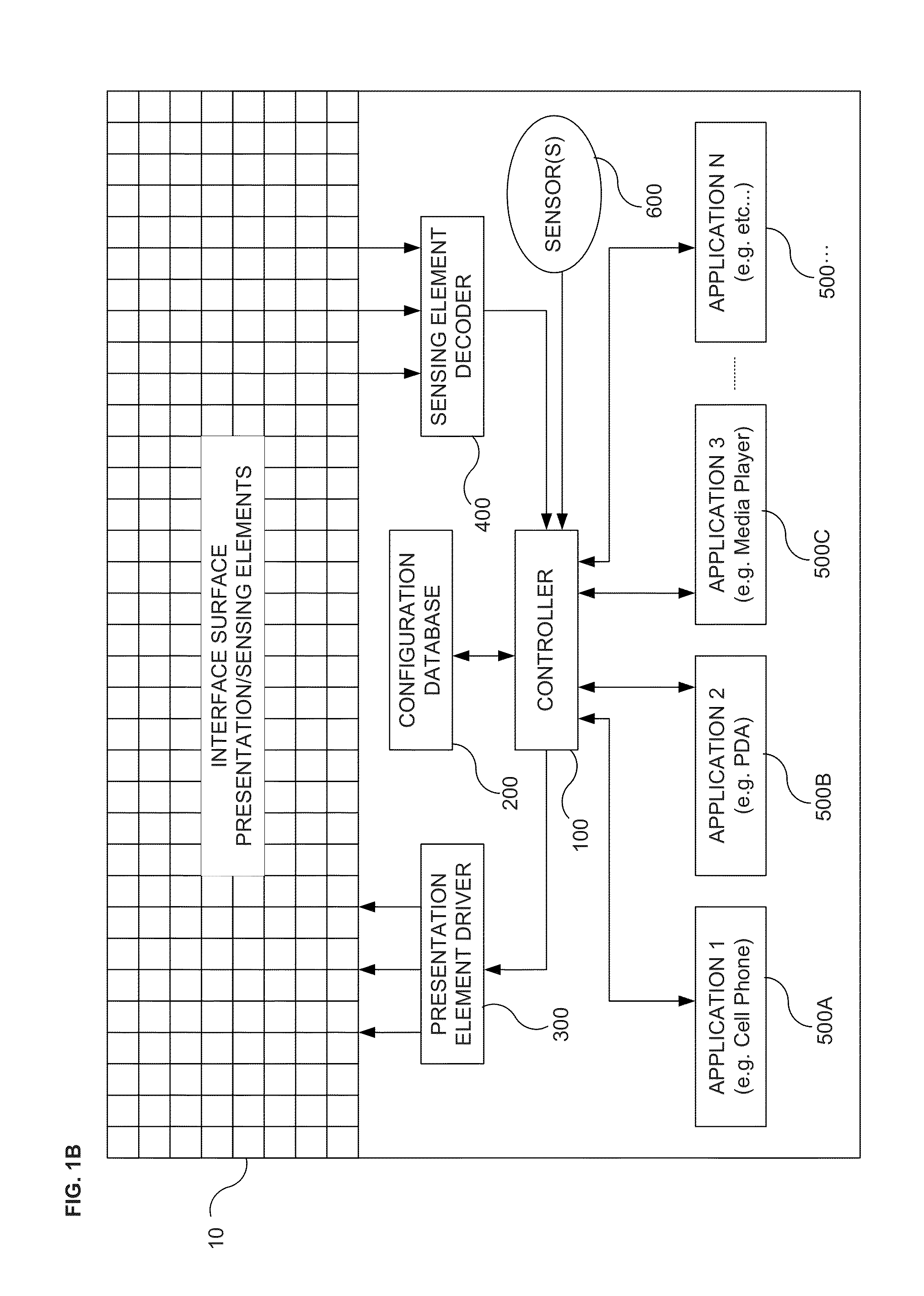

Image

  • Methods, Systems, Apparatuses, Circuits and Associated Computer Executable Code for Detecting Motion, Position and/or Orientation of Objects Within a Defined Spatial Region
  • Methods, Systems, Apparatuses, Circuits and Associated Computer Executable Code for Detecting Motion, Position and/or Orientation of Objects Within a Defined Spatial Region
  • Methods, Systems, Apparatuses, Circuits and Associated Computer Executable Code for Detecting Motion, Position and/or Orientation of Objects Within a Defined Spatial Region

Examples


Embodiment Construction

[0066]In the following detailed description, numerous specific details are set forth in order to provide a thorough understanding of the invention. However, it will be understood by those skilled in the art that the present invention may be practiced without these specific details. In other instances, well-known methods, procedures, components and circuits have not been described in detail so as not to obscure the present invention.

[0067]Unless specifically stated otherwise, as apparent from the following discussions, it is appreciated that throughout the specification discussions utilizing terms such as “processing”, “computing”, “calculating”, “determining”, or the like, refer to the action and / or processes of a computer or computing system, or similar electronic computing device, that manipulate and / or transform data represented as physical, such as electronic, quantities within the computing system's registers and / or memories into other data similarly represented as physical qua...


PUM


Abstract

The present invention includes methods, systems, apparatuses, circuits and associated computer executable code for detecting motion, position and / or orientation of objects within a defined spatial region. According to some embodiments, a defined spatial region (hereinafter also referred to as the: “Active Space”) may be monitored, by any type of appropriate sensor or sensors, and position, orientation and movement of objects within the active space may be determined. Determined position, orientation and movement of objects within the active space may be translated to control signals or other forms of input for an associated computational device.

Description

RELATED APPLICATIONS[0001]This application is a non-provisional application claiming the benefit of: U.S. Provisional Patent Application Ser. Nos. 61 / 585,058 and 61 / 585,147, both filed on Jan. 10, 2012, titled “Methods Circuits Assemblies Systems and Associated Computer Executable Code for Pseudo-Touch Screen Human Machine Interfacing”; and[0002]this application is a continuation in part of:[0003]U.S. patent application Ser. No. 13 / 497,061, titled: “METHODS CIRCUITS APPARATUS AND SYSTEMS FOR HUMAN MACHINE INTERFACING WITH AN ELECTRONIC APPLIANCE”, filed on Mar. 20, 2012, which '061 application is a National Phase of International Application PCT / IL2010 / 000791, filed on Sep. 21, 2010, which International Application claims the benefit of U.S. Provisional Patent Application Ser. No. 61 / 244,136, filed on Sep. 21, 2009; and[0004]this application is a continuation in part of:[0005]U.S. patent application Ser. No. 13 / 734,987, titled: “AN APPARATUS METHOD AND SYSTEM FOR IMAGING”, filed on ...

Claims


Application Information

Patent Timeline
Patent Type & Authority Applications(United States)
IPC IPC(8): G06F3/042
CPCG06F3/0425
Inventor GIVON, DOR
Owner EXTREME REALITY
Why Eureka
Try Eureka