Clamping Element

Active Publication Date: 2013-05-16
VITESCO TECH GMBH
View PDF10 Cites 2 Cited by
  • Summary
  • Abstract
  • Description
  • Claims
  • Application Information

AI Technical Summary

Benefits of technology

[0007]The invention is therefore based on the problem of developing the known method for fastening an electrical conductor on a printed circuit board in such a way that as high a level of

Problems solved by technology

These methods are relatively difficult to automate and generally increased contact resistances arise at the soldered joints, which can lead to the joints being heated, especially when electrical currents with a high current intensity are transmitted.
The heating of these joints between the printed circuit board and the electrical conductor can result in the joint being de

Method used


Image

  • Clamping Element
  • Clamping Element
  • Clamping Element

Examples


Embodiment Construction

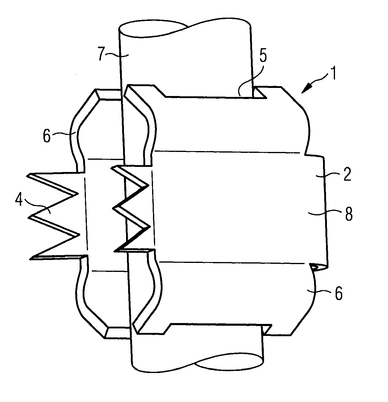
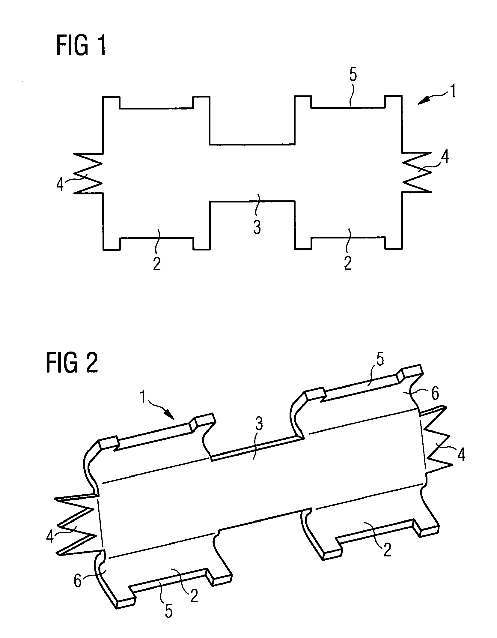
[0025]FIG. 1 shows a clamping element 1 with two clamping wings 2. The two clamping wings 2 are connected to one another by means of the clamping web 3. Securing claws 4 can be seen on the clamping wings 2. Securing claws 4 are shown in the form of trifurcated securing claws 4, in this case, for example. Furthermore, in each case two conductor pockets 5 can be seen on the clamping wings 2. The clamping element 1 itself is in the form of a metallic stamped sheet-metal part, which can be produced extremely inexpensively and easily.

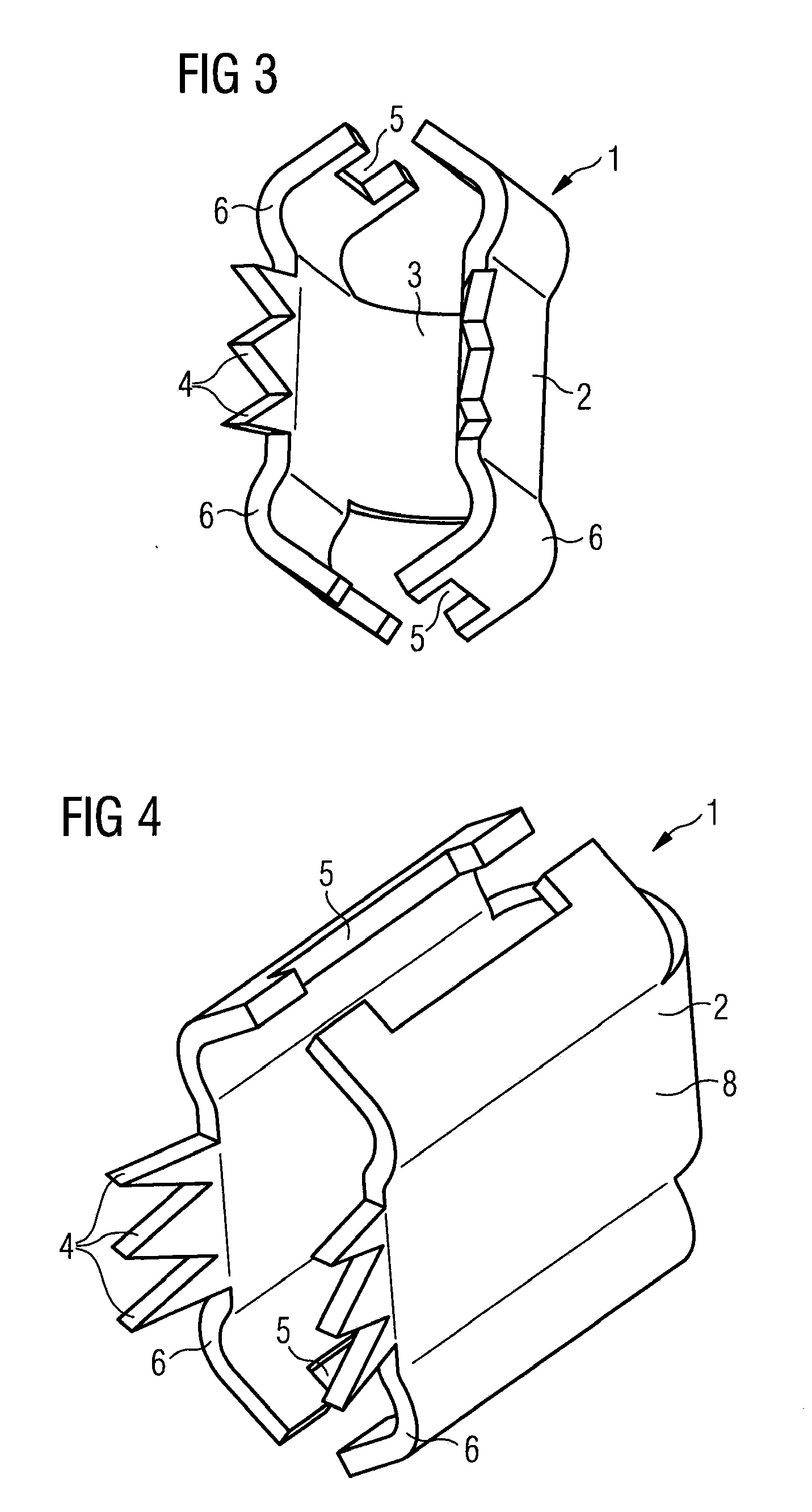
[0026]FIG. 2 shows a development of the clamping element illustrated in FIG. 1. Again, the clamping element 1 has two clamping wings 2, which are connected to one another by the clamping web 3. The clamping wings 2 are now equipped with clamping arches 6, which firstly ensure that an electrical conductor (not illustrated here) is mounted elastically and secondly delimit the contact face 8, which ensures that the clamping element 1 is mounted securely on the ...


PUM


Abstract

A clamping element for fastening an electrical conductor to a printed circuit board, by which electrically conductive connection between the electrical conductor and the printed circuit board is produced. In order to achieve an inexpensive and completely automatable possibility for connection between electrical conductors and printed circuit boards, the clamping element is in the form of a stamped sheet-metal part and has at least two clamping wings and one clamping web, which is arranged between the clamping wings. The clamping web is capable of being bent in such a way that the clamping wings clamp in the conductor. At least one securing claw is formed on the clamping wings. The securing claw can be pressed into the printed circuit board.

Description

CROSS-REFERENCE TO RELATED APPLICATION[0001]This application claims priority to European Application No. EP 11 46 4021,[0002]filed Nov. 14, 2011, the content of which is incorporated by reference herein.BACKGROUND OF THE INVENTION[0003]1. Field of the Invention[0004]The invention is directed to a clamping element for fastening an electrical conductor on a printed circuit board. The invention furthermore is directed to a fastening system for an electrical conductor on a printed circuit board, and to a method for fastening an electrical conductor on a printed circuit board.[0005]2. Description of the Related Art[0006]For many years electronic circuits have been used in the automotive sector, with such electronic circuits usually being arranged on printed circuit boards and serving the purpose of controlling a large number of functions in the automobile. With the increased development of electrically driven vehicles, this tendency is increased, with the demand for currents with high cu...

Claims


Application Information

Patent Timeline
IPC IPC(8): H01R4/28
CPCH01R4/28B60R16/0238H05K3/325H05K2201/10962H01R12/58H05K3/403H05K2201/10287H01R4/26
Inventor BAKOS, TIBOR
Owner VITESCO TECH GMBH
Why Eureka
Try Eureka