Anemometer Detecting Thermal Time Constant of Sensor

a technology of thermal time constant and anemometer, which is applied in the field of solid-state anemometers, can solve the problems of inability to detect the temperature constant of the sensor, the wire is expensive, the thermocouple is expensive, and the calibration is difficult, so as to achieve the effect of less expensive and robust circuitry

Active Publication Date: 2013-05-16
ANALOG DEVICES INT UNLTD
View PDF4 Cites 21 Cited by
  • Summary
  • Abstract
  • Description
  • Claims
  • Application Information

AI Technical Summary

Benefits of technology

[0016]The circuitry is robust since the transistor is encased in a package. The circuit does not need calibration for adequate operation since its construction is very repeatable. The circuit is much less expensive than anemometers using hot wires or thermocouples, and the results are substantially consistent from circuit to circuit and time to time.

Problems solved by technology

Such wires are expensive, are fragile, require frequent cleaning, and require calibration.
Like the hot wires, such thermocouples are expensive, fragile, require frequent cleaning (if exposed), and require calibration.
It is difficult to prevent the diode voltage drop from being affected by the air flow.
Further, the transistor is thermally insulated by its plastic package, making its base-emitter junction slow to respond to changes in air velocity.

Method used


Image

  • Anemometer Detecting Thermal Time Constant of Sensor
  • Anemometer Detecting Thermal Time Constant of Sensor
  • Anemometer Detecting Thermal Time Constant of Sensor

Examples


Embodiment Construction

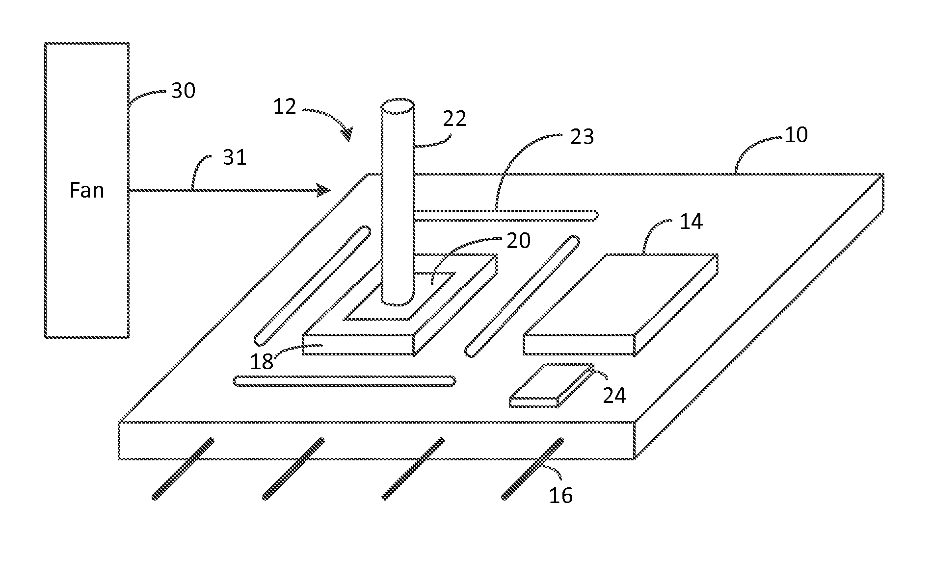
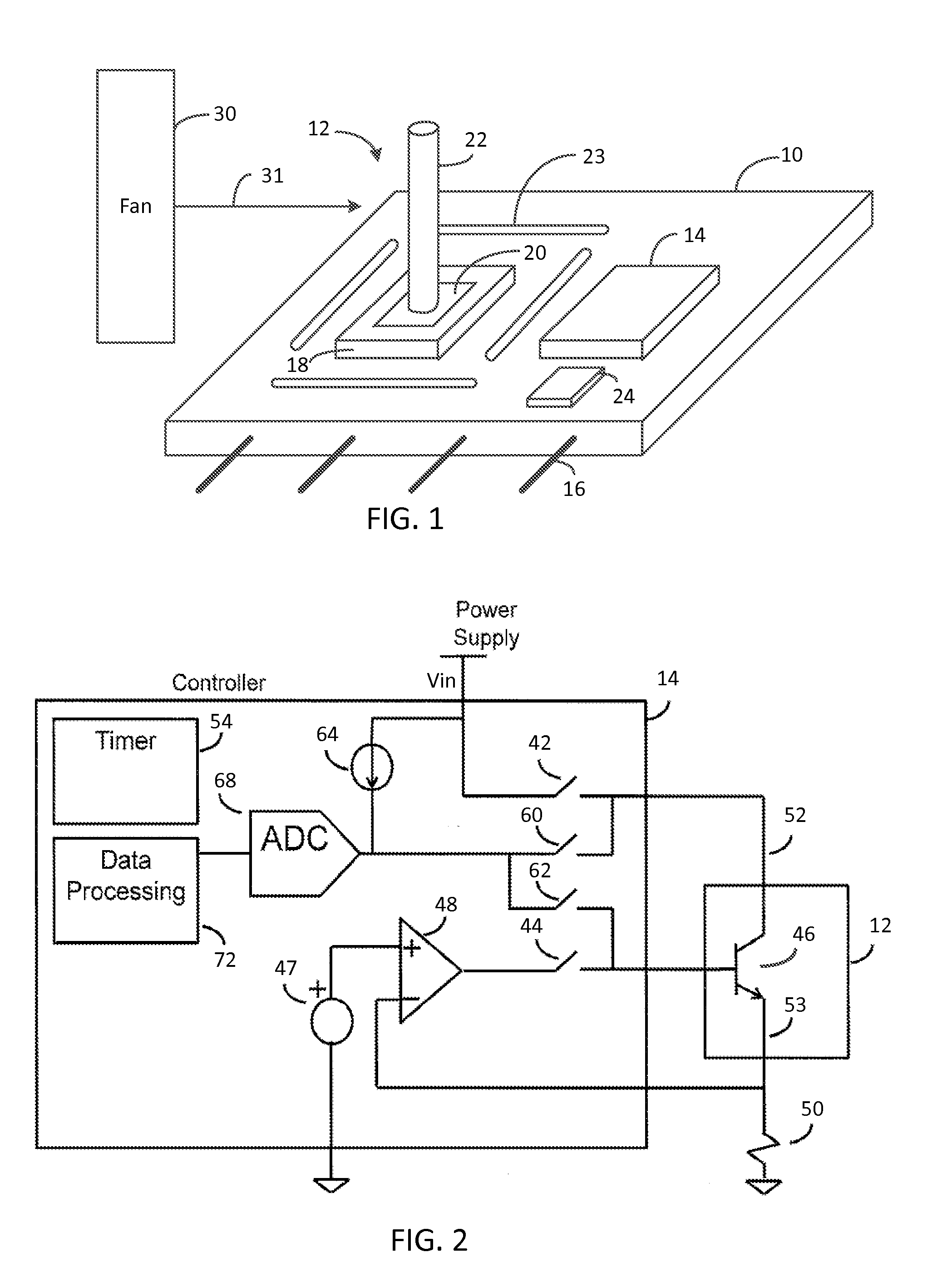
[0028]FIG. 1 illustrates a simplified printed circuit board (PCB) 10 on which is mounted the anemometer sensor 12 and a controller 14. In one embodiment, the PCB 10 is only 3×3 cm or less. The PCB 10 may be conventional and preferably thermally non-conductive. The circuitry on the PCB 10 is connected by copper traces. The PCB's power and I / O pins 16 may be inserted into a socket of a mother board or into a cable connector. In one embodiment, it is desired to know the air flow at various locations in an electrical equipment box, and identical PCBs 10 may be located at various locations in the box.

[0029]A bipolar transistor housed in a package 18 is mounted on the PCB 10. The package may be a surface mount package having three or more terminals

[0030]The package 18 has a metal pad 20 to which the silicon die is thermally coupled. The metal pad 20 is face up. A highly thermally conductive rod 22 is affixed to the thermal pad 20 and acts as a heat sink. In one embodiment, the rod 22 is c...


PUM


Abstract

An anemometer and method for analyzing fluid flow is described. In one embodiment, a transistor sensor is heated by applying power to cause its base-emitter junction to rise from an ambient first temperature to a second temperature. The power is removed, and the Vbe is measured at intervals as the junction cools. The Vbe equates to a temperature of the junction. The temperature exponentially decreases, and the time constant of the decay corresponds to the fluid flow velocity. A best fit curve analysis is performed on the temperature decay curve, and the time constant of the exponential decay is derived by a data processor. A transfer function correlates the time constant to the fluid flow velocity. The transistor is thermally coupled to a metal rod heat sink extending from the package, and the characteristics of the rod are controlled to adjust the performance of the anemometer.

Description

CROSS-REFERENCE TO RELATED APPLICATIONS[0001]This application is based on, and claims priority from, U.S. provisional application 61 / 559,257, filed on Nov. 14, 2011, by the present inventors, entitled Anemometer, assigned to the present assignee and incorporated herein by reference.FIELD OF THE INVENTION[0002]This invention relates to anemometers and, in particular, to a solid state anemometer.BACKGROUND[0003]Anemometers measure the flow of a fluid, such as air, passing over it. In electrical cabinets or boxes containing heat producing circuitry, it is sometimes necessary to provide a fan for cooling. It is conventional to provide instrumentation in the cabinet that monitors temperature and the flow of air. The most common compact anemometers are hot-wires and thermocouples.[0004]The hot-wire type comprises a wire that has a known resistance-temperature characteristic. In one technique, the wire is heated by a current to achieve a target voltage across it and, as air flows over the ...

Claims


Application Information

Patent Timeline
Patent Type & Authority Applications(United States)
IPC IPC(8): G01F1/68G06F19/00
CPCG01P5/10G01F1/698G01F1/688G01P1/00G01P5/02
Inventor HEATH, JEFFREY LYNNKLEEBURG, HARRY JOSEPHSTEWART, HEATH DIXON
Owner ANALOG DEVICES INT UNLTD
Why Eureka
Try Eureka