
System and method for testing magnetic stripe decoding chip

a technology of magnetic stripe and decoding chip, applied in the field of system and method for testing a magnetic stripe decoding chip, can solve the problems of labor and time consumption, and achieve the effects of reducing labor costs, reducing testing time, and improving the efficiency of decoding chip inspection

Inactive Publication Date: 2013-05-23
UNIFORM INDAL CORP
View PDF26 Cites 10 Cited by
  • Summary
  • Abstract
  • Description
  • Claims
  • Application Information

AI Technical Summary

Benefits of technology

The present invention provides a method to reduce the testing time of decoding chips by directly providing a test waveform, which can also be customized for a comprehensive test. This improves the efficiency of inspecting decoding chips and reduces labor costs.

Problems solved by technology

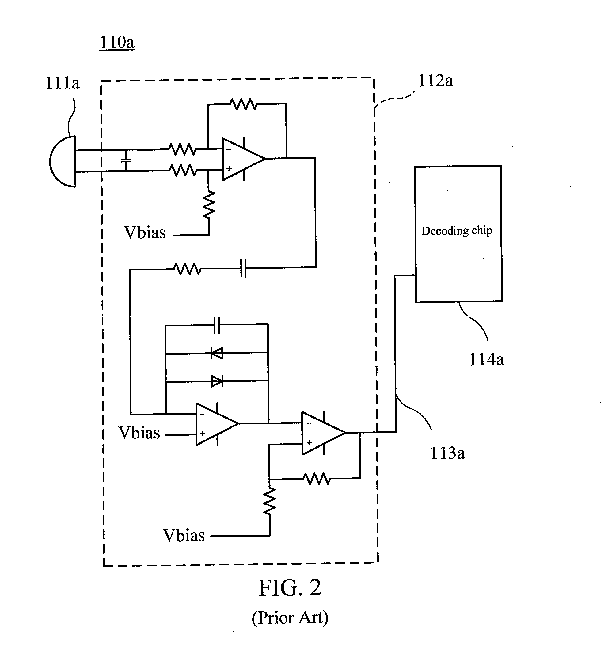
1. To test the reliability of the decoding chip 114a, the decoding chip 114a is required to be tested for many times with different swipe speeds and swipe directions, which is labor and time consuming.

Method used


Image

  • System and method for testing magnetic stripe decoding chip
  • System and method for testing magnetic stripe decoding chip
  • System and method for testing magnetic stripe decoding chip

Examples


Embodiment Construction

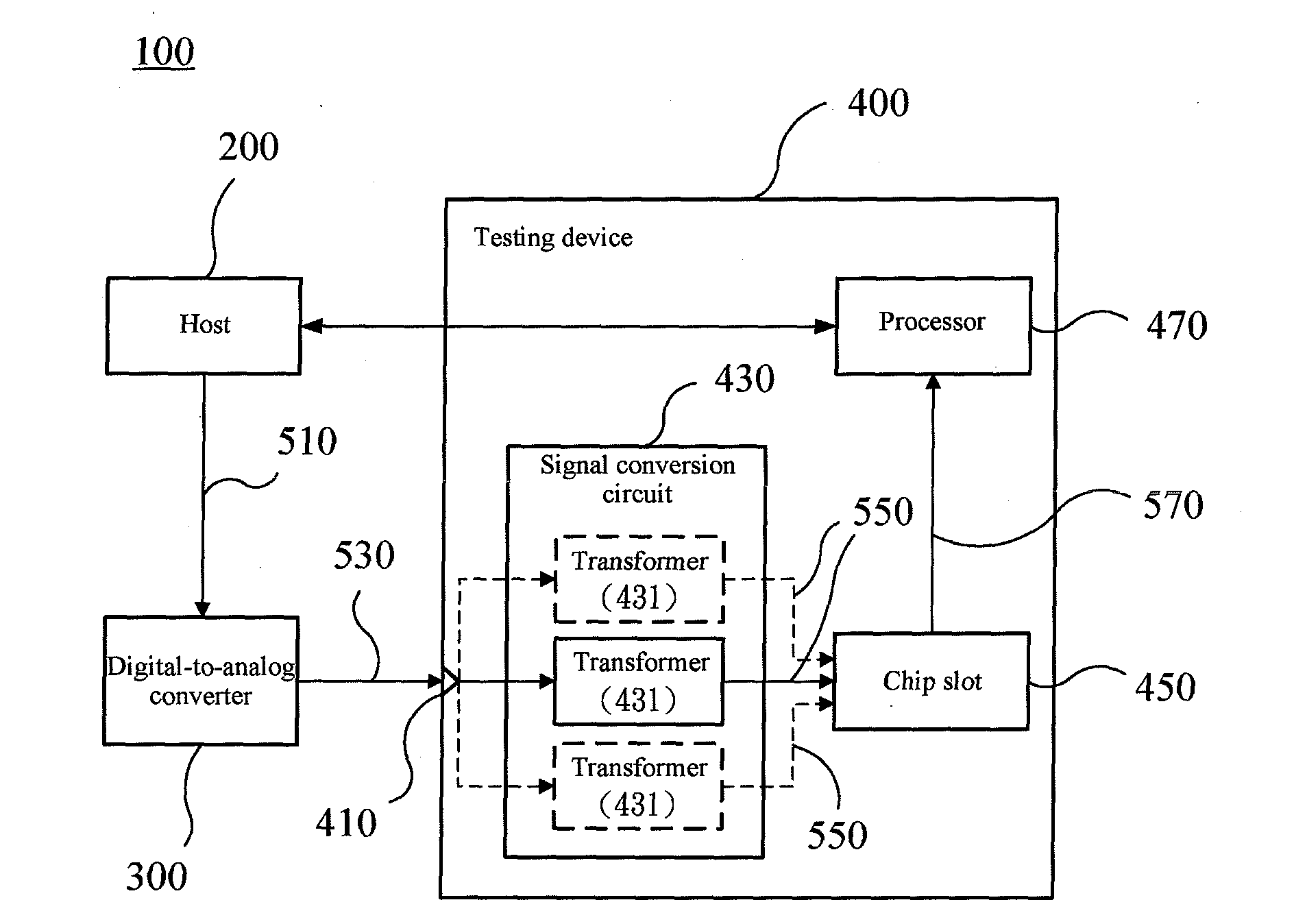
[0027]FIG. 3 is a block diagram of a testing system 100 according to an embodiment of the present invention. As shown in FIG. 3, the testing system 100 includes a host 200, a digital-to-analog converter 300, and a testing device 400. The testing system 100 is configured to test whether a magnetic stripe decoding chip (briefly referred to as a decoding chip below), is normal, that is, test whether the decoding chip can correctly read an encoded signal of a magnetic stripe.

[0028]The digital-to-analog converter 300 is connected electrically to the host 200. The testing device 400 is connected electrically between the host 200 and the digital-to-analog converter 300. Here, the digital-to-analog converter 300 may be a function generator, and the host 200 may be a computer, such as a desktop computer or a notebook computer.

[0029]In an embodiment, the host 200 may be connected to the digital-to-analog converter 300 through a universal serial bus (USB) transmission line. The host 200 may be...


PUM


Abstract

A system and a method for testing a magnetic stripe decoding chip are provided. The system includes a host, a digital-to-analog converter, and a testing device. The host outputs simulation signal data. The digital-to-analog converter receives the simulation signal data and generates a test waveform signal representing a test string. The testing device includes a signal input terminal, a signal conversion circuit, a chip slot, and a processor. The terminal receives the test waveform signal. The chip slot is configured to receive a decoding chip. The circuit includes a transformer connected between the terminal and the chip slot, and is configured to couple the test waveform signal into a pseudo track signal. The processor receives a decoded string generated after decoding the pseudo track signal by the decoding chip. Through comparing the decoded string with the test string, a decoding function of the decoding chip can be determined.

Description

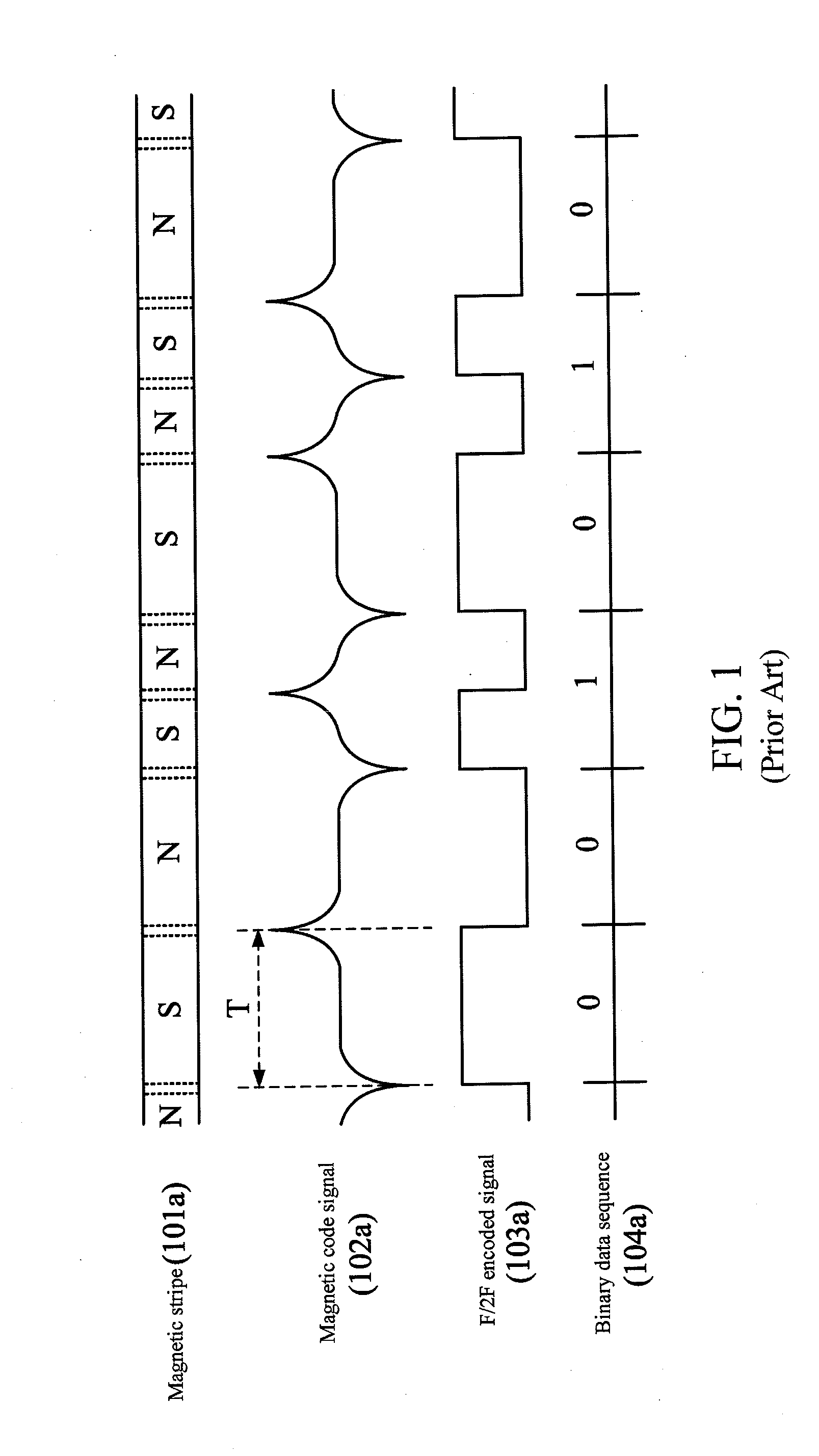
CROSS-REFERENCES TO RELATED APPLICATIONS[0001]This non-provisional application claims priority under 35 U.S.C. §119(a) on Patent Application No. 100142937 filed in Taiwan, R.O.C. on 2011 Nov. 23, the entire contents of which are hereby incorporated by reference.BACKGROUND OF THE INVENTION[0002]1. Technical Field[0003]The present invention relates to a system and a method for testing a chip, and more particularly to a system and a method for testing a magnetic stripe decoding chip.[0004]2. Related Art[0005]FIG. 1 is a diagram of a relation between a magnetic stripe and a decoding signal in the prior art. Generally, a magnetic stripe 101a in a debit or credit card is configured with specifically encoded binary data corresponding to the distribution of magnetic poles on the magnetic stripe. The magnetic stripe may record information by using an encoding technique such as frequency modulation (FM), phase modulation (PM) or double-frequency coherent-phase (F / 2F, also known as Aiken Bipha...

Claims


Application Information

Patent Timeline
IPC IPC(8): G06K7/00
CPCG06K7/0095
Inventor HSU, TUNG-JUNG
Owner UNIFORM INDAL CORP
Learn More