Device and method for inductive power transmission

a technology of inductive power transmission and inductive power, applied in the direction of inductances, transformers, instruments, etc., can solve the problems of eddy current loss, remagnetization loss and hysteresis loss, damage to foreign objects, transmitting units and/or receiving units, etc., to achieve reliable power absorbed indication, low complexity, and low complexity

Inactive Publication Date: 2013-05-23
ROBERT BOSCH GMBH
View PDF11 Cites 35 Cited by
  • Summary
  • Abstract
  • Description
  • Claims
  • Application Information

AI Technical Summary

Benefits of technology

[0012]In one exemplary embodiment of the method, the presence of a foreign object between the device and the power receiver is inferred when the input current is above the threshold value. An input current of the power component which is above a threshold value is advantageously a reliable indication of power absorbed between the device and the power receiver.
[0013]It is advantageous that the resonant frequency is varied to a value between 250 kHz and 1 MHz. This frequency range is advantageously a definite distance away from a frequency range between 25 kHz and 150 kHz, which is used for power transmission, and has proven suitable in experiments and for detection of even small foreign objects.
[0014]In one exemplary embodiment of the method, the resonant frequency is varied by varying a capacitance of the oscillating circuit. The variation in the capacitance of the oscillating circuit may advantageously be implemented with low complexity in terms of the technical circuitry.
[0015]In another exemplary embodiment of the method, the resonant frequency is varied by varying an inductance of the oscillating circuit. The variation in inductance of the oscillating circuit is advantageously also possible with low complexity in terms of the technical circuitry.
[0016]In a preferred exemplary embodiment of the method, the method is carried out before the device begins with a power transmission to a power receiver. This advantageously ensures that any foreign object situated between the device and the power receiver will not be heated by a power transmission.
[0017]In an additional exemplary refinement of the method, this is performed repeatedly and periodically during a power transmission to a power receiver. In this way, also a subsequent introduction of a foreign object into an area between the device and a power receiver may advantageously be detected.

Problems solved by technology

The physically induced voltage in the foreign object results in eddy current losses and, in the case of ferromagnetic materials in particular, remagnetization losses and hysteresis losses.
The foreign object is then heated to a high temperature under some circumstances, which may result in damage to the foreign object, the transmitting unit and / or the receiving unit.
This also entails a risk of injury to anyone present in the surroundings.
This is done on the basis of the knowledge that a power absorbed in the foreign object and therefore a power loss will increase with an increase in the frequency of the magnetic alternating field.

Method used


Image

  • Device and method for inductive power transmission
  • Device and method for inductive power transmission
  • Device and method for inductive power transmission

Examples


Embodiment Construction

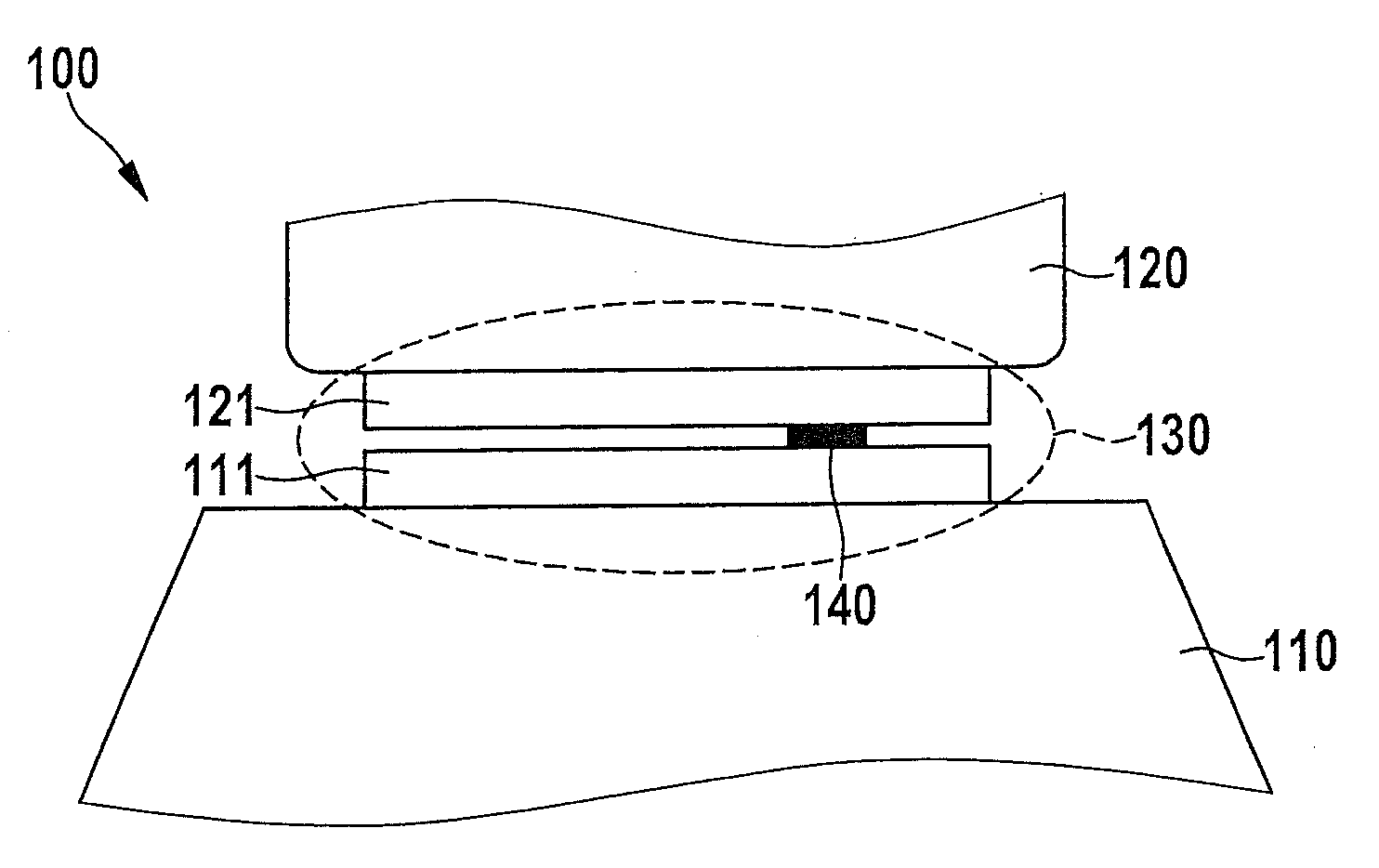
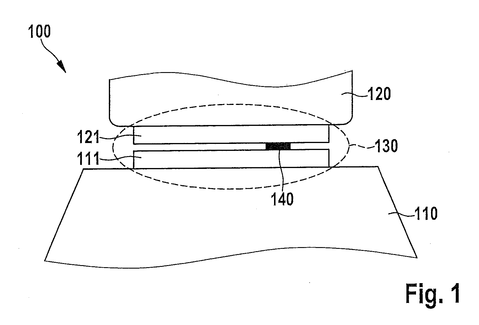
[0021]FIG. 1 shows a highly schematized diagram of a system 100 for inductive power transmission. System 100 for inductive power transmission includes a device 110 for inductive power transmission and a power receiver 120. Device 110 for inductive power transmission may be a charging device or a charging cradle, for example. Power receiver 120 may be, for example, a cordless small electrical device. For example, power receiver 120 may be an electric toothbrush or a cell phone.

[0022]Device 110 for inductive power transmission is designed to charge an energy store of power receiver 120, for example, a battery pack or an accumulator pack without a cable connection between device 110 for inductive power transmission and power receiver 120. Device 110 for inductive power transmission has a transmitting unit 111 for this purpose. Power receiver 120 has a receiving unit 121. Transmitting unit 111 and receiving unit 121 are designed to be able to approach each other except for a small dista...


PUM

PropertyMeasurementUnit
resonant frequencyaaaaaaaaaa
frequencyaaaaaaaaaa

Abstract

A device for inductive power transmission includes an oscillating circuit having an inductance and a capacitance, a power component for exciting an electric oscillation in the oscillating circuit, a determination unit for determining an input current of the power component, and a frequency shifting unit designed to vary a resonant frequency of the oscillating circuit.

Description

CROSS REFERENCE TO RELATED APPLICATION[0001]The present application claims priority to Application No. DE 10 2011 086 904.2, filed in the Federal Republic of Germany on Nov. 23, 2011, which is expressly incorporated herein in its entirety by reference thereto.FIELD OF INVENTION[0002]The present invention relates to a device for inductive power transmission, and a method for operating such a device.BACKGROUND INFORMATION[0003]Devices and methods for inductive power transmission are known from the related art. Such devices are used for charging batteries of small electrical equipment. A magnetic field is used for power transmission between a transmitting unit (charging station) and a receiving unit (battery pack).[0004]Known devices for inductive power transmission are usually designed as resonant converters. Resonant converters include essentially a resonant capacitance and a resonant inductance, together forming a resonant transformer. The resonant frequency of the resonant transfor...

Claims


Application Information

Patent Timeline
Patent Type & Authority Applications(United States)
IPC IPC(8): H01F38/14
CPCH01F38/14H02J5/005G01V3/101H02J7/025H02J50/12H02J50/60H02J7/02
Inventor LOHR, GUENTERMACK, JUERGEN
Owner ROBERT BOSCH GMBH
Why Eureka
Try Eureka