Rotary compressor and manufacturing method thereof

a technology of rotary compressor and manufacturing method, which is applied in the direction of machines/engines, liquid fuel engines, positive displacement liquid engines, etc., can solve the problems of reducing the performance of the compressor, reducing the noise and vibration of the compressor, and reducing the noise so as to enhance the performance and reliability of the compressor. , the effect of reducing the vibration and noise of the rotary compressor

Inactive Publication Date: 2013-05-23
SAMSUNG ELECTRONICS CO LTD
View PDF15 Cites 9 Cited by
  • Summary
  • Abstract
  • Description
  • Claims
  • Application Information

AI Technical Summary

Benefits of technology

[0010]Therefore, it is an aspect of the present disclosure to provide a rotary compressor capable of improving the performance thereof and reducing noise and vibration thereof.
[0019]The rotary compressor may further include an accumulator configured to filter a liquefied refrigerant, and a suction tube configured to supply refrigerant gas from the accumulator to the compression portion. The suction tube may be formed with flexible material to prevent vibration and noise of the compression portion from being delivered to the case.
[0020]The rotary compressor may further include a suction tube to supply refrigerant gas to the compression portion. The suction tube may be formed in an elongated manner so that the suction tube is bent at an inside the case to prevent noise and vibration of the compression portion from being delivered to the case.
[0027]As described above, vibration and noise of a rotary compressor may be reduced, thereby enhancing the performance and reliability of the compressor. Accordingly, a rotary compressor may be used for various fields other than for an air conditioner.

Problems solved by technology

At this time, the aligning of the compression portion and the driving portion may be twisted, and in a case when the aligning is twisted, the performance of the compressor is decreased and noise is developed from the compressor.
In addition, as the driving portion is press-fitted to the case, the noise and vibration of the driving portion and compression portion are delivered to the case, thereby resulting in greater noise and vibration when compared to other types of compressors.

Method used


Image

  • Rotary compressor and manufacturing method thereof
  • Rotary compressor and manufacturing method thereof
  • Rotary compressor and manufacturing method thereof

Examples


Embodiment Construction

[0032]Reference will now be made in detail to the embodiments of the present disclosure, examples of which are illustrated in the accompanying drawings, wherein like reference numerals refer to like elements throughout.

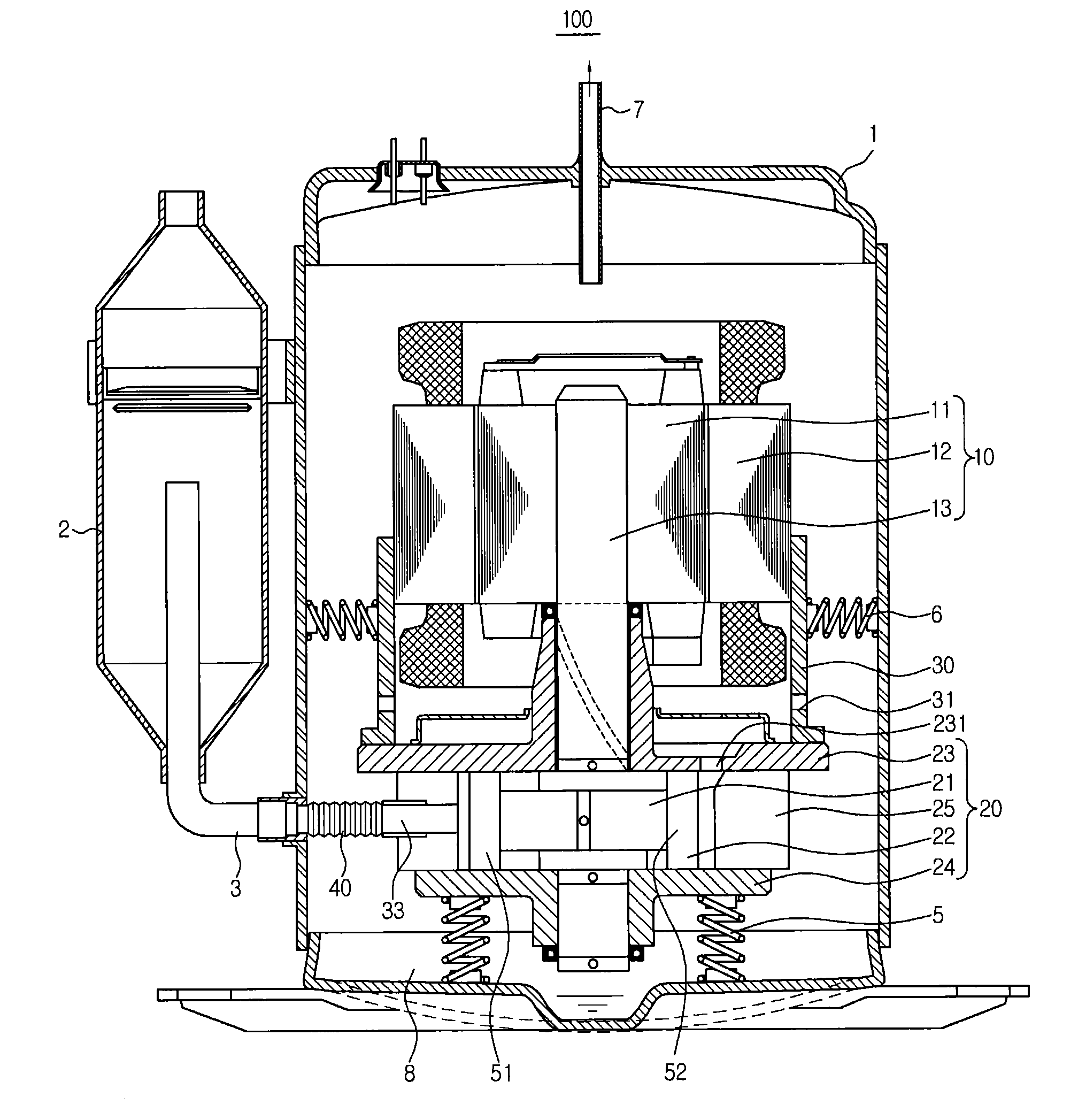
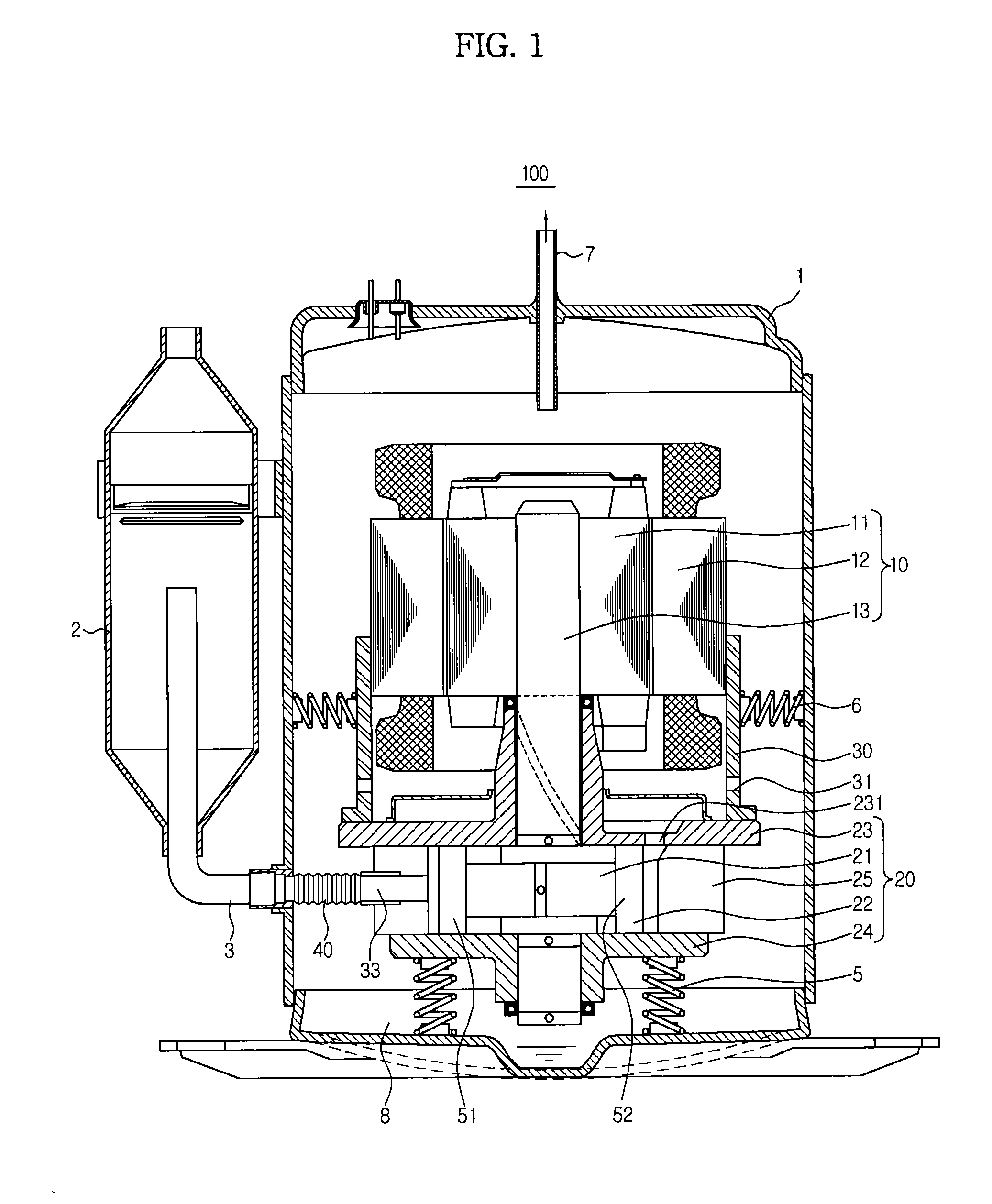
[0033]FIG. 1 is a drawing illustrating a rotary compressor in accordance with one embodiment of the present disclosure.

[0034]As illustrated on FIG. 1, a rotary compressor 100 according to the embodiment of the present disclosure includes a case 1 forming an exterior, a driving portion 10 to generate a driving power, and a compression portion 20 to compress refrigerant gas by receiving the driving power of the driving portion 10. The driving portion 10 and the compression portion 20 are installed at an inside of the case 1 which is sealed and has the shape of a cylinder.

[0035]One side of a lower portion of the case 1 is connected to a suction tube 40 that is configured to supply refrigerant gas from an accumulator 2 to the compression portion 20. The accumulator 2 is c...


PUM

PropertyMeasurementUnit
flexibleaaaaaaaaaa
distanceaaaaaaaaaa
heataaaaaaaaaa

Abstract

A rotary compressor having a reduced vibration and noise thereof, and capable of minimizing the deformation of components to improve the performance and the reliability, thereby providing applications for various fields other than for an air conditioner

Description

CROSS-REFERENCE TO RELATED APPLICATIONS[0001]This application claims the benefit of Korean Patent Application No. 2011-0121146, filed on Nov. 18, 2011 in the Korean Intellectual Property Office, the disclosure of which is incorporated herein by reference.BACKGROUND[0002]1. Field[0003]Embodiments of the present disclosure relate to a rotary compressor, and more particularly, to a rotary compressor having an enhanced support structure thereof.[0004]2. Description of the Related Art[0005]In general, a compressor is an apparatus configured to compress a fluid such as air or refrigerant by applying a pressure thereon by receiving a power from a driving apparatus such as an electric motor and to discharge the compressed fluid, and is used in a product such as an air conditioner or a refrigerator.[0006]A compressor is divided into a positive displacement-type compressor and a turbo-type compressor, and the positive displacement-type compressor includes a rotary compressor configured to com...

Claims


Application Information

Patent Timeline
Patent Type & Authority Applications(United States)
IPC IPC(8): F04C18/02B23P11/00
CPCF04C18/0207B23P11/00Y10T29/49245F04C2270/12F04C18/356F04C23/008F04C18/344F04C29/00F04C29/06
Inventor LEE, JEONG BAE
Owner SAMSUNG ELECTRONICS CO LTD
Why Eureka
Try Eureka