
Method of fabrication for an asymmetric bragg coupler-based polymeric wavelength filter with single-grating waveguide

a technology of asymmetric bragg coupler and asymmetric bragg coupler, which is applied in the direction of optical waveguide light guide, coating, instruments, etc., can solve the problems of limiting the application range of wdm network, expensive fabrication equipment, and difficult engraving of the grating on the bottom of either waveguide, so as to achieve reliable and accurate

Inactive Publication Date: 2013-05-23
NAT FORMOSA UNIV
View PDF2 Cites 7 Cited by
  • Summary
  • Abstract
  • Description
  • Claims
  • Application Information

AI Technical Summary

Benefits of technology

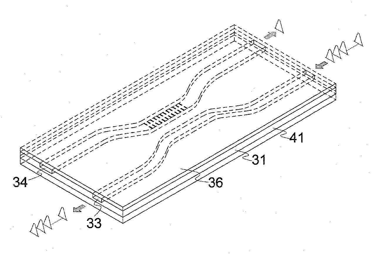
The present invention is about a method to make polymeric waveguide filters using an asymmetric Bragg coupler with single-grating waveguide. This method involves first creating a master mold of the coupler on a negative photo-resist mold, then injecting a PDMS film into the narrow waveguide of the coupler to act as a protection layer. Gratings patterns are then exposed on the alternative waveguide and transferred to PDMS stamp mold. The final filter is formed using UV cured polymer. The process is reliable and accurate and can lead to mass production of grating structures on either waveguide of the waveguide couplers in the filter.

Problems solved by technology

However, they generally suffer from either a narrow free spectral range (FSR), or an expensive fabrication equipment, that restrict its application range in WDM networks.
However, the device has a disadvantage that the gratings were engraved concurrently on the bottoms of a pair of dissimilar waveguides, embedded into a planar substrate, and therefore an undesired reflection wavelength, denoted by self-reflection Bragg wavelength, caused by the grating of input waveguide was occurred in the input end.
Due to the close proximity of the two waveguides, engraving the grating on the bottom of the either waveguide is much more difficult than that of the both ones.

Method used


Image

  • Method of fabrication for an asymmetric bragg coupler-based polymeric wavelength filter with single-grating waveguide
  • Method of fabrication for an asymmetric bragg coupler-based polymeric wavelength filter with single-grating waveguide
  • Method of fabrication for an asymmetric bragg coupler-based polymeric wavelength filter with single-grating waveguide

Examples


Embodiment Construction

[0029]I. The Basic Fabrication Process of the Present Invention

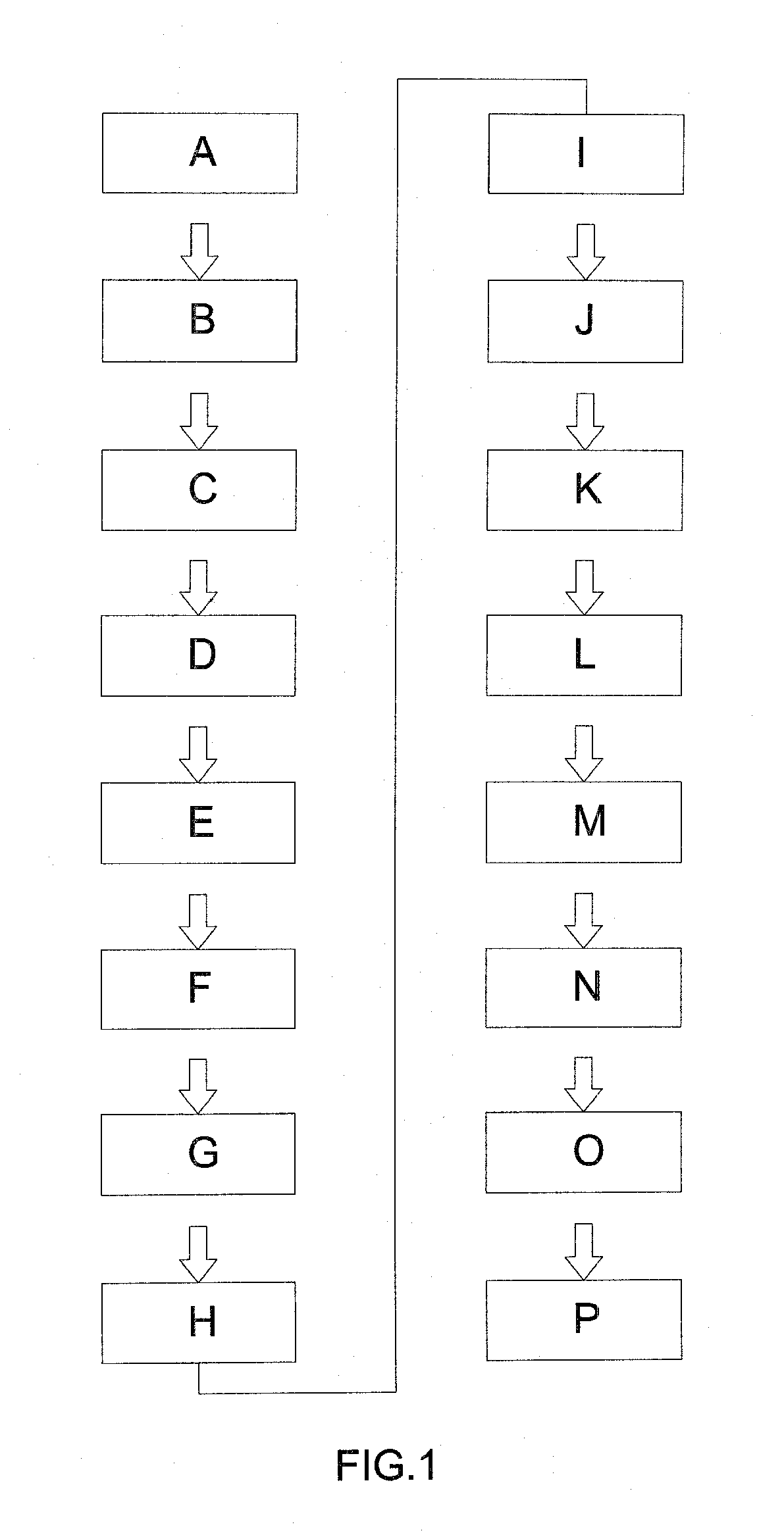
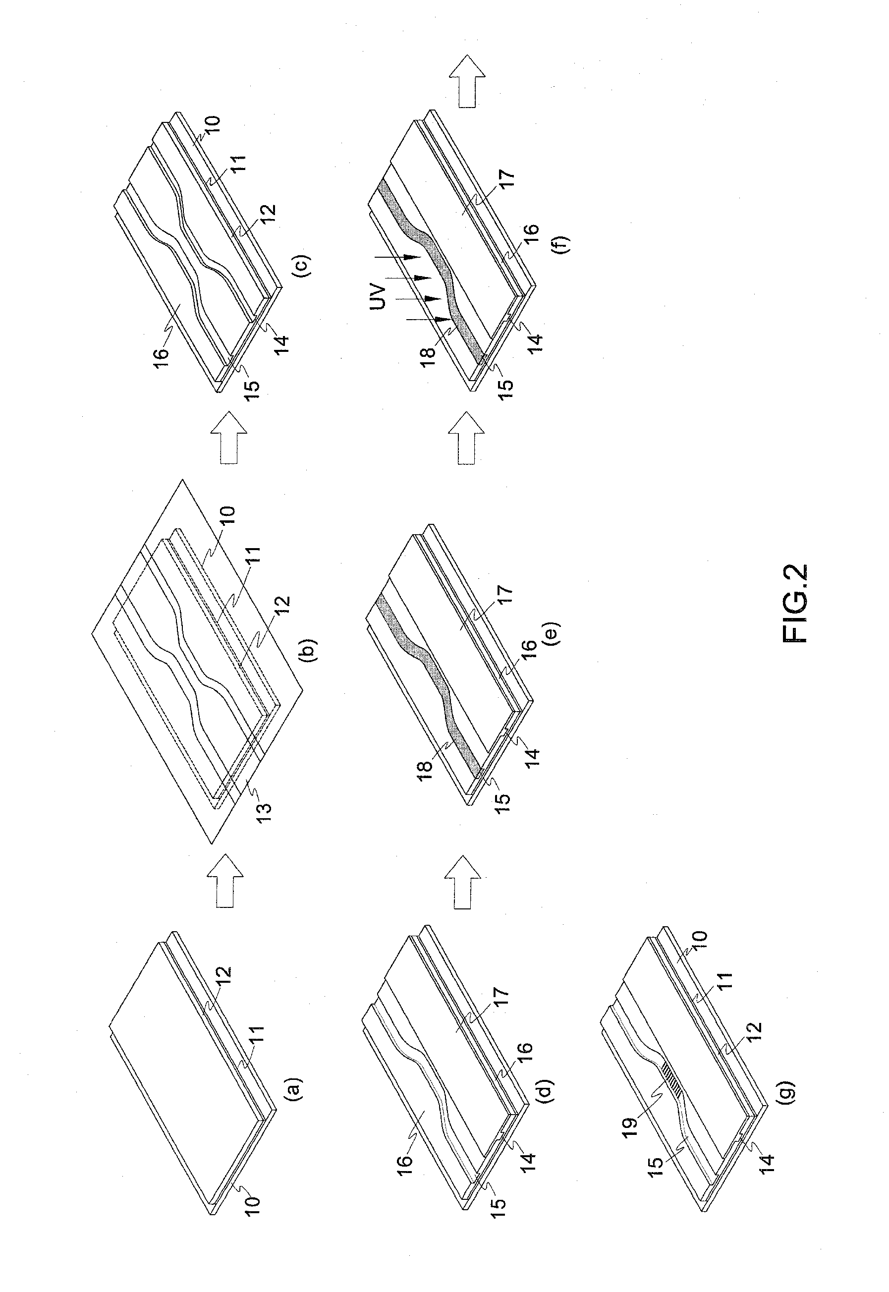
[0030]Referring to FIGS. 1 to 5, the basic method for fabricating the polymer wavelength filter of the present invention comprises following steps:

[0031](A) depositing a UV polymer film 11 and a negative photo-resist film 12 on a glass substrate 10 (referring to FIG. 2(a));

[0032](B) the negative photo-resist film 12 being exposed by UV light through a photo mask 13 to obtain a negative photo-resist mold 16 having a first groove 14 and a second groove 15, the widths of the two grooves 14 / 15 being different from each other (referring to FIGS. 2(b) and 2(c));

[0033](C) depositing a first PDMS film 17 on the half area of the top of the negative photo-resist mold 16 and being filled in the first groove 14 of the negative photo-resist mold 16, and baking the first PDMS film 17 (referring to FIG. 2(d));

[0034](D) depositing specific amount of positive photo-resist 18 in the second groove 15 (referring to FIG. 2(e));

[0035](E) expo...


PUM

PropertyMeasurementUnit
Temperatureaaaaaaaaaa
Lengthaaaaaaaaaa
Lengthaaaaaaaaaa

Abstract

The present invention discloses a method for fabricating polymeric wavelength filter based on an asymmetric Bragg coupler with single-grating waveguide. The asymmetric waveguide coupler is formed firstly on a negative photo-resist mold. PDMS film is injected into the narrow waveguide of the coupler to act as a protection layer. The gratings pattern is exposed on the alternative waveguide and subsequently transferred to PDMS stamp mold. The PDMS stamp mold is used as a stamp to transfer the gratings pattern of the ABC wavelength filter onto UV cured polymer to form the final ABC filter. Whereby, the fabrication process is reliable and accurate, and can offer great potential for mass production of the ABC filter with single-grating waveguide.

Description

FIELD OF THE INVENTION[0001]The present invention relates to a method for fabricating asymmetric Bragg coupler-based polymeric wavelength filter with single-grating waveguide, especially to a technique that uses the micro-molding process to simplify the fabrication process for obtaining an ABC filter with good aspect ratio of gratings pattern.BACKGROUND OF THE INVENTION[0002]As well known, optical add / drop multiplexer (OADM) devices, enabling the flexible insertion (add) or extraction (drop) of a specific wavelength in optical fiber communications, have been indispensable components for wavelength division multiplexing (WDM)-based networks, accommodating large bandwidths for the global spread multimedia communications. These components not only allow the extraction of a wavelength from a transmission loop and the addition of the same wavelength to the network, but also, monitor the signals in transparent networks to identify and locate the possible failures. Numerous different archi...

Claims


Application Information

Patent Timeline
IPC IPC(8): C08J7/04
CPCC08J7/04G02B6/12007G02B6/1221G02B6/124G02B6/13
Inventor CHUANG, WEI-CHING
Owner NAT FORMOSA UNIV
Learn More