

Blade and Housing Assembly
a technology of blades and housings, applied in the direction of electrical equipment, electrical discharge tubes, coupling device connections, etc., can solve the problems of physical stress on the components of these smart devices, impairing the ability of the devices to function in their intended manner, etc., to achieve the effect of stable devices, sufficient stability and resistance to stress
- Summary
- Abstract
- Description
- Claims
- Application Information
AI Technical Summary
Benefits of technology
Problems solved by technology
Method used
Image

Examples
first embodiment
[0022] the present invention provides an assembly for stabilization of blades. A “blade” is a structure that comprises, consists essentially of or consists of an electrically conductive material such as a metal or a metal alloy, including but not limited to bronze, phosphor bronze, brass or copper. In known technologies, when accessing electricity from a power source (e.g., an AC power source), typically a device is connected directly or indirectly to a plug that comprises two blades. In some embodiments of the present invention, the blades are oriented as NEMA 5 series blades that provide access to a power source.
[0023]As persons of ordinary skill in the art are aware, often within a plug a grounding pin is associated with a pair of blades. In some embodiments of the present invention, the grounding pin that is associated with the blades that access a power source is part of an earth redirector. An “earth redirector” serves the purpose of grounding the device through a first pin an...
second embodiment
[0043] the present invention is directed to an assembly that comprises at least one appliance claw, for example two appliance claws for each pair of appliance blades. Each appliance claw has a length, a width and a height, and each appliance claw comprises the following regions: a foot, a spine and a wedge. Each appliance claw may have no axes of symmetry or one axis of symmetry.
[0044]The length is the longer dimension that is parallel to the base. The width is the same size as the length or shorter than the length and is also is parallel to the base. The height is the dimension that is perpendicular to the base. In some embodiments, the overall length of an appliance claw is 0.5 to 2 cm, the width is 0.4 to 1.5 cm, and the height is 0.75 to 3 cm. When an appliance claw does not have a uniform length, width or height, the aforementioned dimensions refer to the largest length, width or height respectively.
[0045]The foot is configured to stabilize the appliance claw and spans the leng...
third embodiment
[0061]The assembly of the third embodiment may also comprise a printed circuit board. The printed circuit board may be or may be part of an outlet monitoring device. The outlet monitoring device may be a single port or multi-port outlet monitoring device.
[0062]The various embodiments of the present invention may be further illustrated by the accompanying figures.
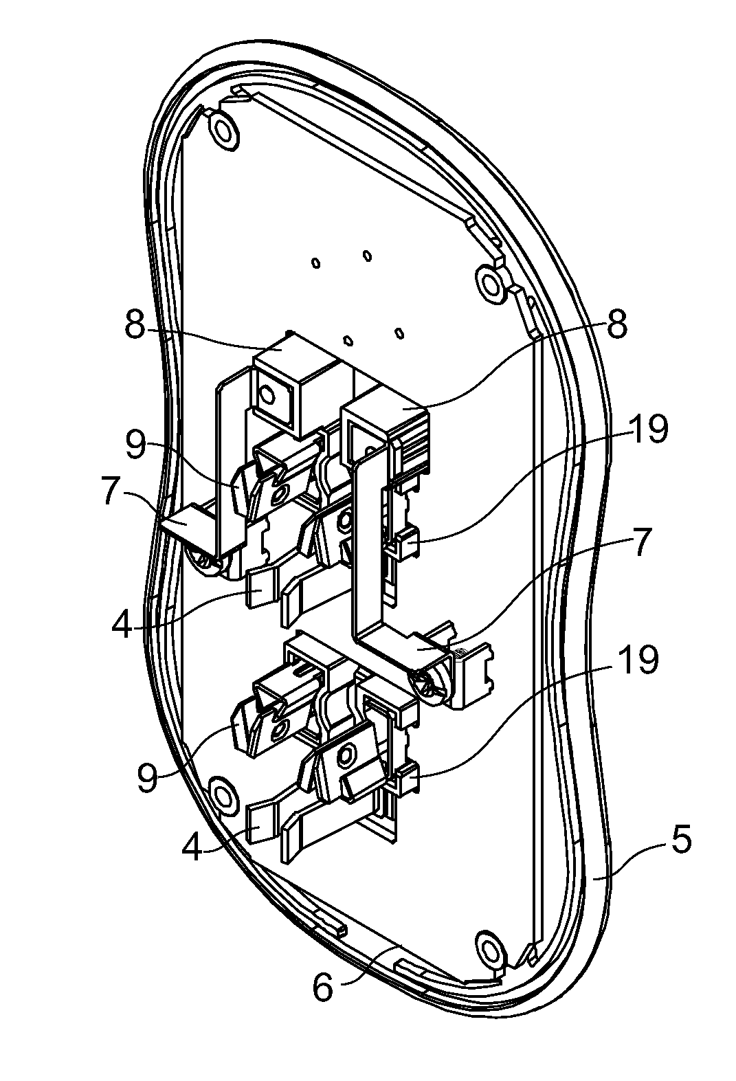
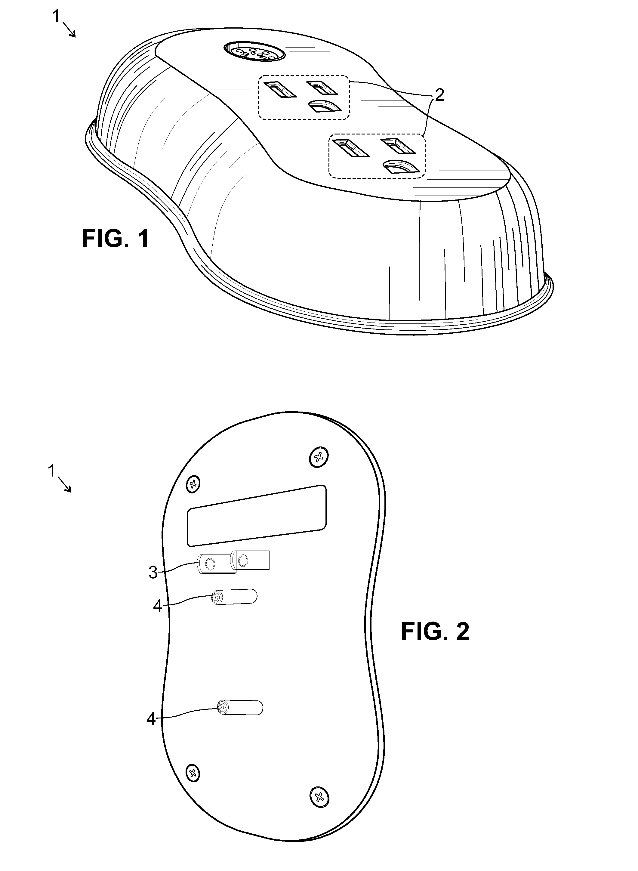
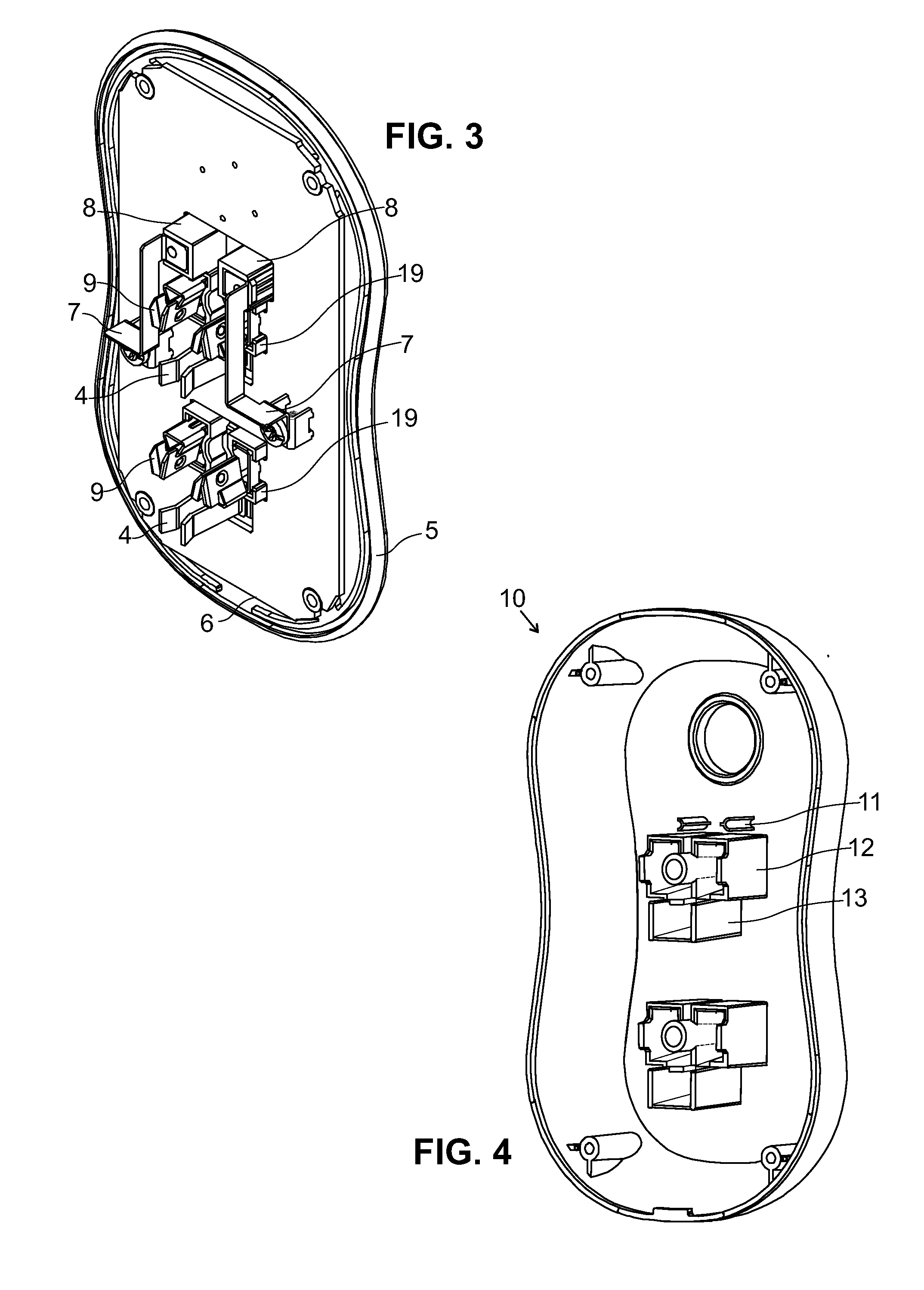
[0063]FIG. 1 shows a multi-port outlet monitoring device 1 of the present invention from a front view. The cover and base are engaged and there are openings 2 for the blades and grounding pins of two different appliances. Through the internal circuitry, the use of each of the two appliances can be monitored and analyzed.
[0064]FIG. 2 shows the multi-port outlet monitoring device 1 of FIG. 1 from the rear. A pair of blades 3 is shown. The blades are designed to be inserted into a source of electricity, e.g., an outlet. Also shown are two pins of an earth redirector 4. Notably, there are two pins but only one pair of blades. Th...
PUM
 Abstract
Description
Claims
Application Information