Multiple PLC simulation system

a simulation system and logic controller technology, applied in the field of multi-plc simulation systems, can solve the problems of complex equipment cannot be implemented as software, and the delay of introducing a new automated system may incur a great loss of profit and credibility of a manufacturer, so as to reduce the cost of plc code verification and simplify the environment settings for plc control simulation in units of lines

Active Publication Date: 2013-05-23
UDMTEK
View PDF1 Cites 9 Cited by
  • Summary
  • Abstract
  • Description
  • Claims
  • Application Information

AI Technical Summary

Benefits of technology

[0019]According to a multiple PLC simulation system in accordance with an embodiment of the present invention, a plurality of software PLCs which are PLCs that control lines and equipment in an automated manufacturing system and are implemented as software connected through a single network, and simulation is performed for verification of a plurality of PLC codes. Consequently, drawbacks of a conventional simulation method for PLC code verification in which lines and equipment of an automated manufacturing system are divided on the basis of a unit of PLC control and simulation is performed for verification of individual software PLC codes that correspond to each PLC control unit may be enabled to be solved. More specifically, in the conventional simulation method, a network communication environment cannot be established between a plurality of software PLCs that control the lines and the equipment because simulation for code verification is allowed to be performed by each PC for one software PLC according to a PLC vender type, and as a result, verification of errors and abnormal states which may occur during communication of input / output signals between each software PLC and human machine interface (HMI) cannot be carried out.
[0020]Moreover, a network consisting of the software PLCs substitute for a conventional
[0021]OLE for process control (OPC) server and hardware PLCs which are connected to the OPC server to perform a conventional simulation for PLC code verification in units of lines, and hence, environment settings for implementing PLC control simulation in units of lines can be simplified and cost for PLC code verification can be reduced.

Problems solved by technology

With the development of industries, a conventional automated manufacturing system needs to be changed into a new automated manufacturing system, and the delay of introduction of a new automated system may incur a great loss of profit and credibility of a manufacturer.
However, since the control program may have inherent human error, the manufacturing control operator needs to test the automated manufacturing system prior to the test running with respect to ladder diagram that includes the PLC code.
However, in the simulation method shown in FIG. 1 in which the lines of the automated manufacturing system are divided on the basis of a unit of PLC control and simulation is performed for verification of individual software PLC codes that correspond to each PLC control unit, the automated manufacturing system that controls a plurality of the lines and the equipment cannot be implemented as software because the simulation for code verification is allowed to be performed by each PC for only one software PLC according to a PLC vender type.
Moreover, the aforementioned simulation method in which the verification of one software PLC code is performed by one PC cannot verify errors and abnormal states which may occur during communication of input / output signals between each software PLC and human machine interface (HMI) in an actual automated manufacturing system that consists of a network of PLCs.
On the other hand, in a case where a plurality of the hardware PLCs are connected to the OPC server and simulation is performed for PLC code verification in units of lines as shown in FIG. 2, control logic configuration based on a plurality of the hardware PLCs may allow the PLC control simulation in units of lines, while environment settings for the PLC control simulation are complex and cost for PLC code verification is increased due to a communication environment established by a plurality of the hardware PLC and the OPC server.

Method used


Image

  • Multiple PLC simulation system
  • Multiple PLC simulation system
  • Multiple PLC simulation system

Examples


Embodiment Construction

[0026]The following description is provided to assist the reader in gaining a comprehensive understanding of the methods, apparatuses, and / or systems described herein. Accordingly, various changes, modifications, and equivalents of the methods, apparatuses, and / or systems described herein will be suggested to those of ordinary skill in the art. Also, descriptions of well-known functions and constructions may be omitted for increased clarity and conciseness.

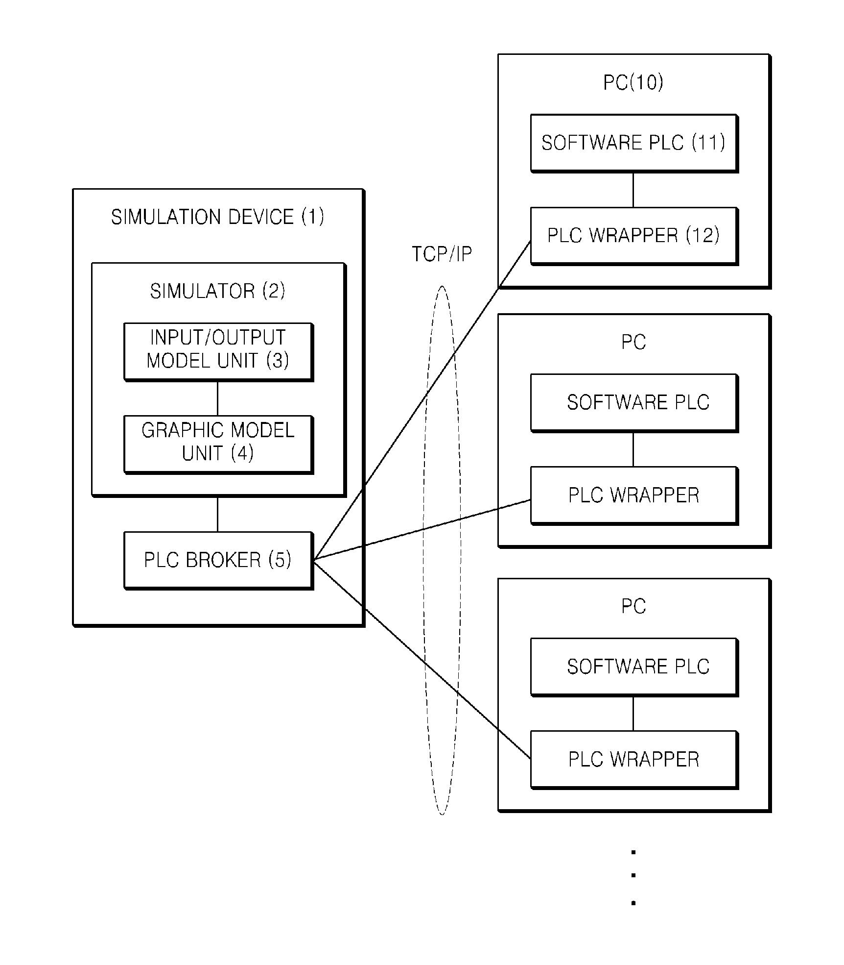
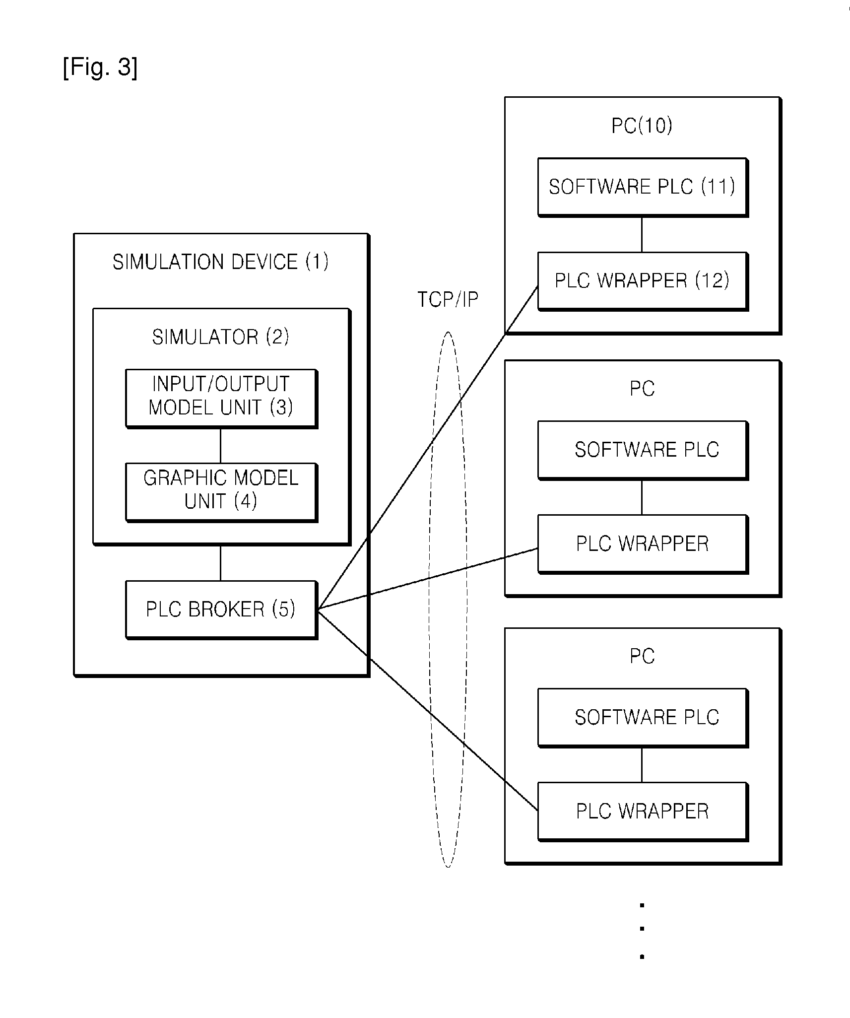
[0027]FIG. 3 illustrates an example of a configuration of a multiple programmable logic controller (PLC) system according to an exemplary embodiment.

[0028]Referring to FIG. 3, the multiple PLC simulation system may include a simulation device 1 and a plurality of personal computers (PCs) 10.

[0029]A plurality of the PCs 10 may include different software PLCs which are PLCs implemented as software to verify a plurality of PLC codes that generate PLC input signals and PLC output signals for controlling lines and equipment in the auto...


PUM


Abstract

A multiple programmable logic controller (PLC) simulation system is provided. The multiple PLC simulation system includes a plurality of personal computers (PCs), each being configured to comprise a different software PLC which is one of a plurality of PLCs implemented as software in an effort to verify a plurality of PLC codes that generate a PLC input signal and a PLC output signal for controlling lines and equipment of an automated manufacturing system; and a simulation device configured to be connected to a plurality of the PCs over a network, and to perform simulation for verification of a plurality of the PLC codes using an input/output model and a graphic model where the input/output model defines as discrete events operation states of the lines and the equipment which are controlled according to the PLC output signals received from a plurality of the software PLCs and PLC input signals in accordance with the operation states, and the graphic model represents graphically motion change of the lines and the equipment in accordance with a change of operation states using pieces of motion graphic data of the lines and the equipment which correspond to the operation states and the graphic model generates PLC input signals including information on the motion change of the lines and the equipment.

Description

TECHNICAL FIELD[0001]The following description relates to a programmable logic controller (PLC) simulation system, and more particularly, to a simulation technique for verifying a plurality of PLC codes by implementing a plurality of PLCs as software, which control lines and equipment of an automated manufacturing system, and connecting the PLCs over a single network.BACKGROUND ART[0002]As industries have been rapidly developed and advanced, an automated manufacturing system is evolving fast than ever. With the development of industries, a conventional automated manufacturing system needs to be changed into a new automated manufacturing system, and the delay of introduction of a new automated system may incur a great loss of profit and credibility of a manufacturer.[0003]Various automated equipment which constitute an automated manufacturing system are controlled and operated by a programmable logic controller (PLC). The PLC stores therein ladder diagram information as a control pro...

Claims


Application Information

Patent Timeline
Patent Type & Authority Applications(United States)
IPC IPC(8): G06F17/50
CPCG05B19/05G06F17/5022G06F9/455G06F30/33
Inventor WANG, GI NAMKWAK, JONG GEUN
Owner UDMTEK
Why Eureka
Try Eureka