Power plant with co2 capture and method to operate such power plant

a power plant and co2 technology, applied in steam engine plants, machines/engines, mechanical equipment, etc., can solve problems such as the reduction of the efficiency of the power plant as a whole, and achieve the effect of increasing efficiency and improving reliability of operation

Active Publication Date: 2013-05-30
GENERAL ELECTRIC TECH GMBH
View PDF4 Cites 12 Cited by
  • Summary
  • Abstract
  • Description
  • Claims
  • Application Information

AI Technical Summary

Benefits of technology

[0006]It is an object of the invention to provide a power plant for the generation of electrical energy comprising a plant for the capture and compression of CO2, where such plant has an increased efficiency as a whole and a higher degree of reliability of operation of the CO2 capture plant compared to power plants of this type known in the prior art.

Problems solved by technology

Such use of high-pressure steam results however, in a reduction in efficiency of the power plant as a whole due to the loss of high-pressure steam in the turbines driving the generator.

Method used


Image

  • Power plant with co2 capture and method to operate such power plant
  • Power plant with co2 capture and method to operate such power plant
  • Power plant with co2 capture and method to operate such power plant

Examples


Embodiment Construction

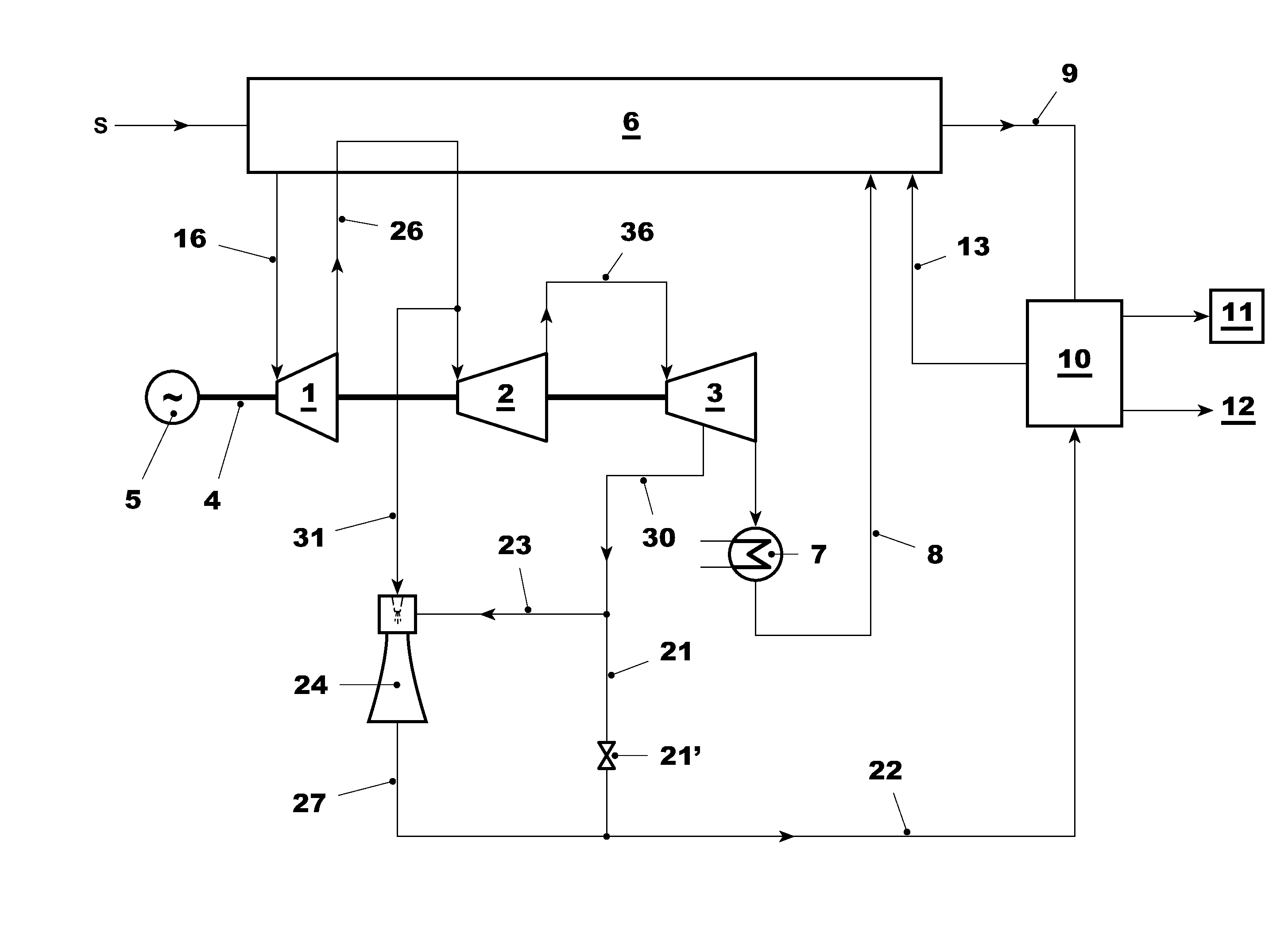
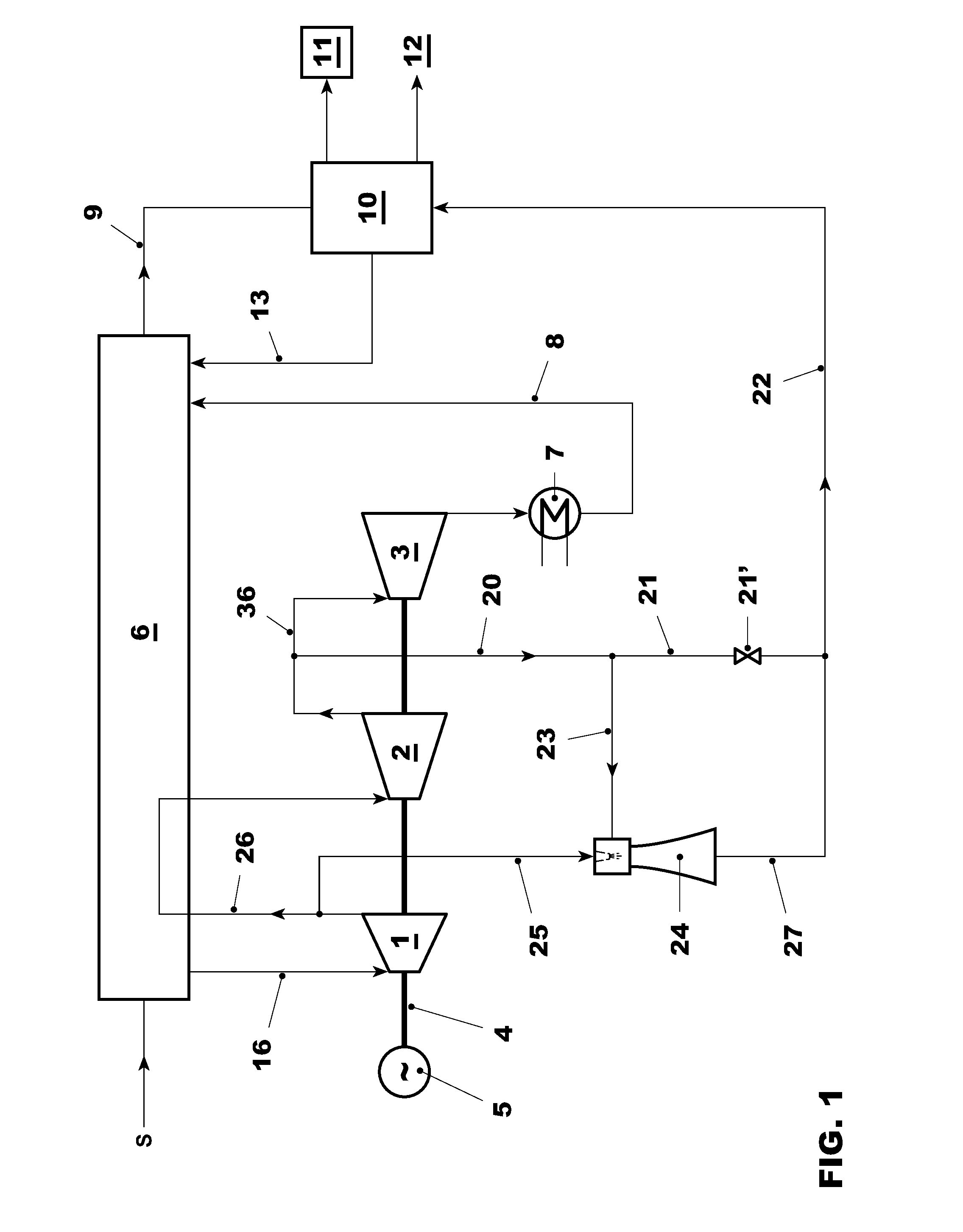
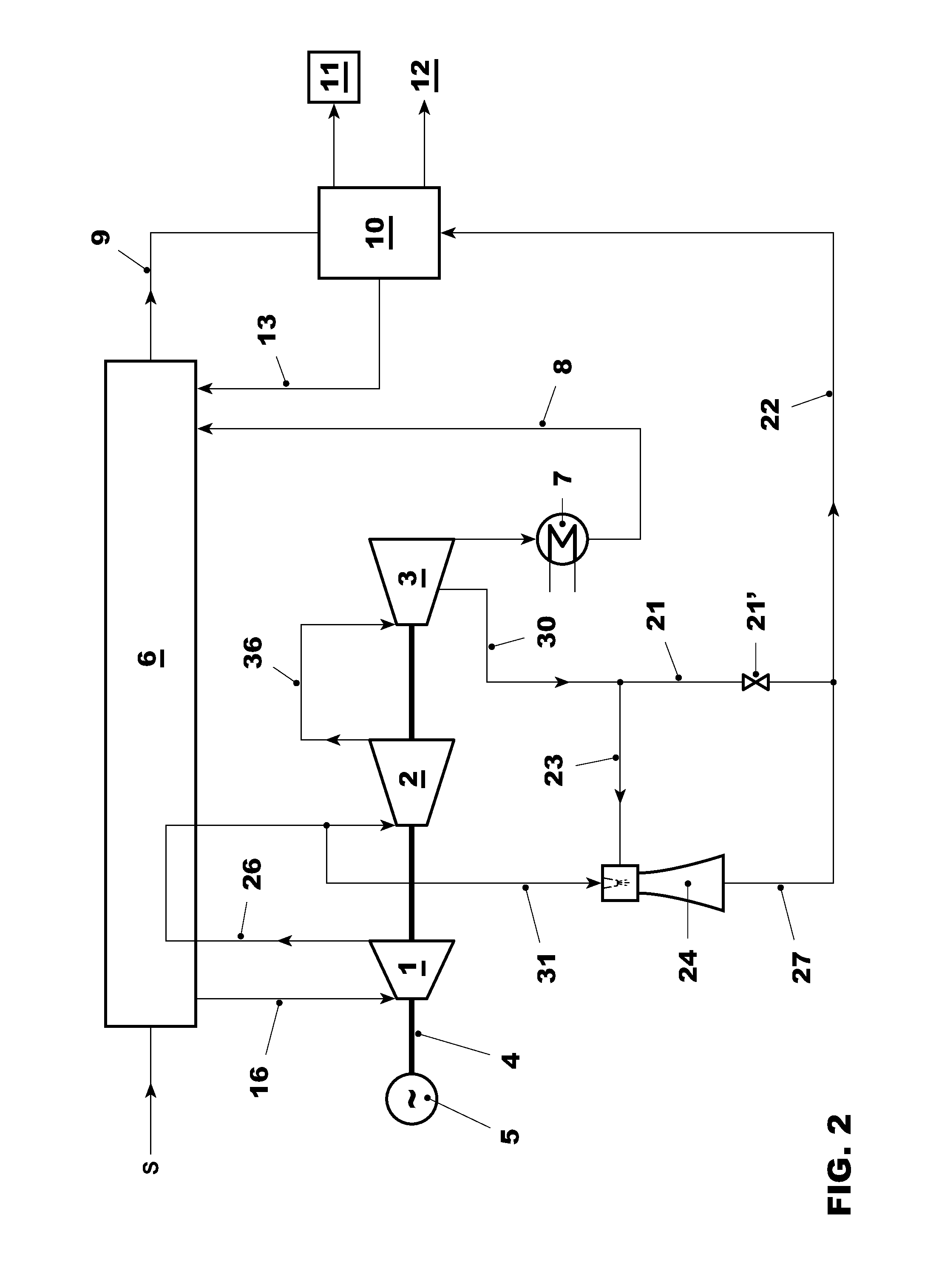
[0032]FIGS. 1-3 each show a power plant according to the invention having steam turbines 1, 2, and 3 driven by high-, intermediate-, and low-pressure steam respectively. The steam turbines are arranged on a common shaft 4 to drive a generator 5 for the generation of electrical energy. The steam for the turbines is generated by a boiler fired by a fossil fuel or a steam generator such as a heat recovery steam generator HRSG 6 operated by means of the hot exhaust gases from a gas turbine S. The live steam is fed via a line 16 to the high-pressure steam turbine 1. The steam turbines 1, 2, and 3 are connected via reheat and cross-over steam lines 26 and 36, respectively. The water steam cycle of the power plant of FIGS. 1-3 is completed by a condenser 7, which condenses the steam exhausted by the low-pressure steam turbine 3, specified apparatuses (not shown) for the reheating and degassing of the condensate and feedwater a return line 8 leading to the boiler or HRSG 6.

[0033]The power p...


PUM


Abstract

A fossil fuel fired power plant for the generation of electrical energy comprises a water steam cycle and a plant (10) for the capture of CO2 from exhaust gases emitted by the power plant and a steam jet ejector (24) configured and arranged to receive an input steam flow from a low- or intermediate pressure extraction point in the power plant and to increase its pressure. It is further arranged to receive motive steam (25) from a further extraction point in the power plant. A steam line (27, 22) directs the steam of increased pressure from the steam jet ejector (24) to the CO2 capture plant (10). The power plant according to this invention allows the use of low-pressure steam for the operation of the CO2 capture plant, where the extraction of such steam affects the overall efficiency of the power plant to a lesser degree than in power plant of the state of the art.

Description

TECHNICAL FIELD[0001]The present invention pertains to a fossil fuel fired power plant for the generation of electrical energy comprising a plant for the capture of carbon dioxide resulting from the combustion of the fossil fuels. It pertains in particular to an apparatus providing steam used for operating the carbon dioxide capture plant. It furthermore pertains to a method of operating such power plant.BACKGROUND ART[0002]Power plants for the generation of electrical energy based on the combustion of fossil fuels have been proposed to include plants for the capture of carbon dioxide (CO2) produced in order to reduce the emission of this gas into the atmosphere known to significantly contribute to the green house effect. Most recently, the operation of such power plants has started in pilot projects.[0003]Known carbon capture plants include a CO2 absorber operating on the basis of chilled ammonia or amine processes and furthermore several CO2 compressors in order to compress the ca...

Claims


Application Information

Patent Timeline
Patent Type & Authority Applications(United States)
IPC IPC(8): F01K17/04
CPCF01K23/064F01K17/04Y02E20/32F01K23/06
Inventor JONSSON, STAFFANLI, HONGTAOCONTE, ENRICO
Owner GENERAL ELECTRIC TECH GMBH
Why Eureka
Try Eureka