Horizontal well line-drive oil recovery process

a technology of horizontal wells and oil recovery, applied in the direction of fluid removal, earth-moving drilling, borehole/well accessories, etc., can solve the problems of insufficient steam generation at the surface, inability to produce fresh water, and inability to meet the needs of oil recovery, so as to achieve uniform gas delivery, effective free oil trapped, and uniform oil collection

Inactive Publication Date: 2013-05-30
CAPRI PETROLEUM TECH
View PDF2 Cites 7 Cited by
  • Summary
  • Abstract
  • Description
  • Claims
  • Application Information

AI Technical Summary

Benefits of technology

[0022]Alternatively, both the injection and production wells may be placed with the respective heel and toe portions in mutually juxtaposed position. In such case it is then preferred to use internal tubing to inject the gas at the toe of the injection well, thereby moving the high pressure source from the heel of the injection well to its toe. In such manner the high pressure source will be at an end of the reservoir opposite the low pressure heel of the production well, thereby forcing the gas to travel a longer distance through the formation and thereby more effectively free oil trapped in the formation, so as to then travel and be collected by the low pressure area at the heel of the production well. Such configuration has the benefit of requiring only a single drilling pad located on the same side of the reservoir, since the vertical portion of the injector wells and the producer wells will all be on the same side of the reservoir.
[0023]In addition to the empl

Problems solved by technology

A serious drawback of steam processes is the inefficiency of generating steam at the surface because a considerable amount of the heat generated by the fuel is lost without providing useful heat in the reservoir.
Several other drawbacks occur with steam-based oil recovery processes: natural gas may not be available to fire the steam boilers, fresh water may be scarce and clean-up of produced water for recycling to

Method used


Image

  • Horizontal well line-drive oil recovery process
  • Horizontal well line-drive oil recovery process
  • Horizontal well line-drive oil recovery process

Examples


example 1

Staggered Well Configuration

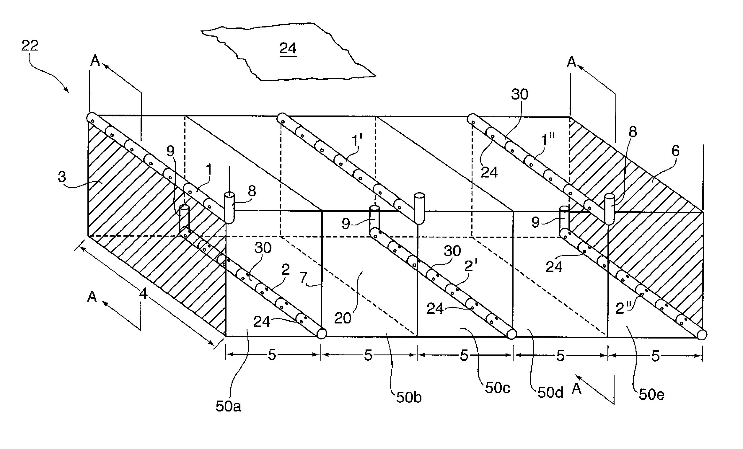
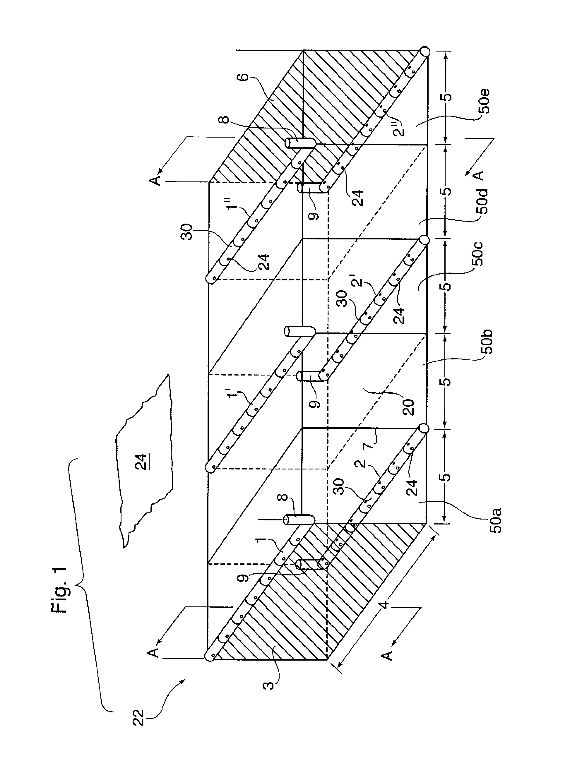
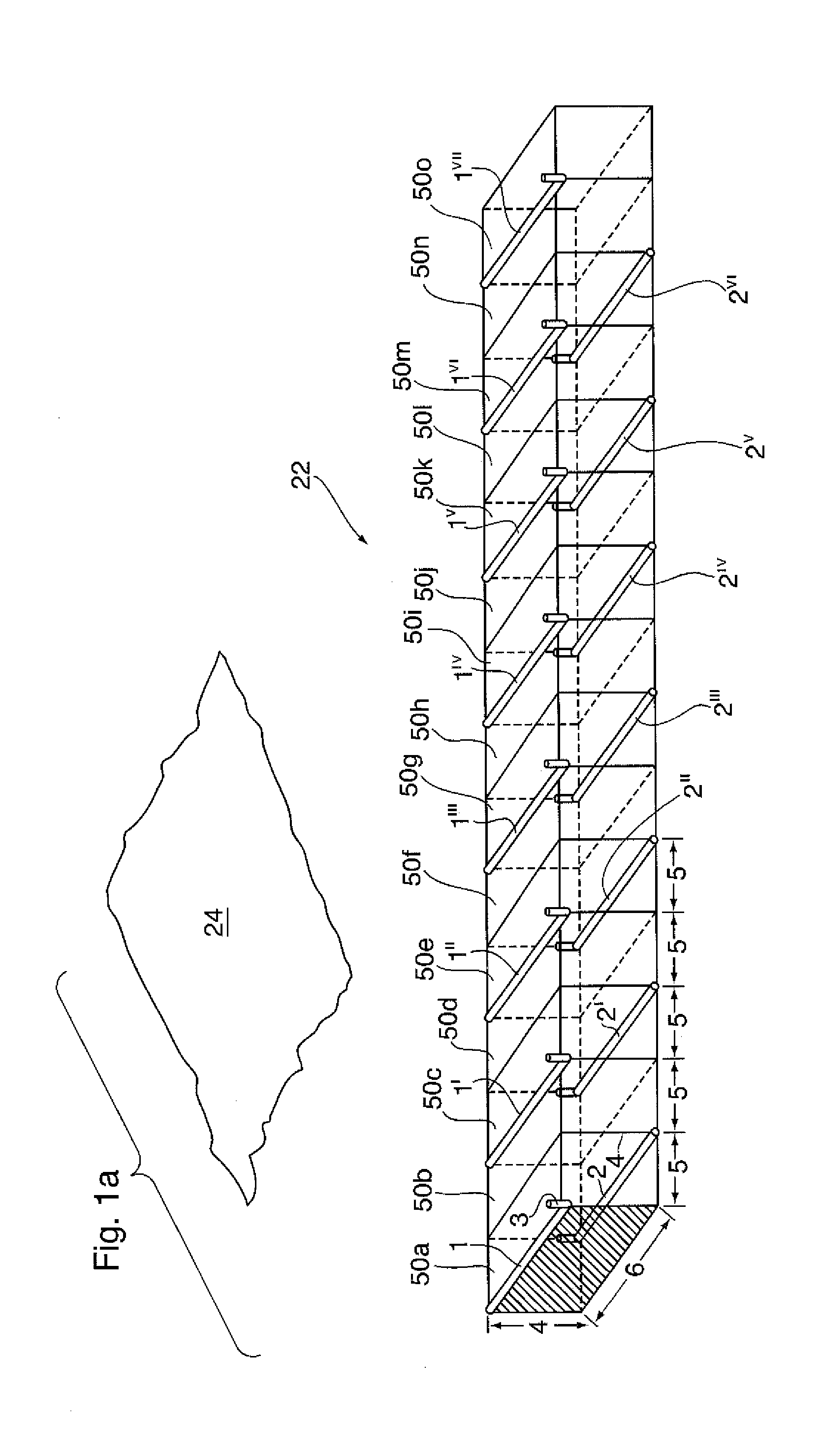
[0110]For the Staggered Well configuration, the oil containing portion 20 of reservoir 22 comprising grid blocks 50a-50o shown in FIG. 1A was s divided into three equal parts, each consisting of five grid blocks 50a-e, 50f-j, and 50k-o, as shown in FIG. 1. Each equal part was successively exploited in three separate but successive phases, each phase taking 5 years, using the wells in FIG. 1 over a 15-year period. The total reservoir volume exploited over the 15-years process life is 1,500,000 m3.

[0111]For the Staggered Well Pattern shown in FIG. 1, a first part of the three part modelling used 2.5 injection wells 1, 1′, and 1″, and 2.5 production wells 2, 2′, and 2″, all simultaneously drilled, for a total of five wells. The reservoir thickness 4 was 20 m and the well offset was 50 m for each grid block 50a-50o. Air injection rates were 10,000 m3 / d for well 1 and 20,000 m3 / d for each of injectors 1′ and 1″, for a total of 50,000 m3 / d for the pattern.

[0112...

example 2

HWLD Well Configuration

[0113]For the HWLD process which was modelled using computer simulation, and as shown in FIG. 4b, in a first phase (FIG. 4b(i)] a horizontal injector well 1 is located high in the formation, and a horizontal well 2 located low in the reservoir 22 is provided, both being placed along one side of the oil containing portion 20 of reservoir 22.

[0114]In FIG. 4b and FIG. 11, representing the HWLD process and configuration of the method of the present invention, the well lengths 6 were each 100 m, the reservoir thickness, 4, was 20 m and the well offset was 100 m. The total volume of reservoir produced over the 15-year exploitation period was thus also 1,500,000 m3.

[0115]The air injection rate was 16,667 m3 / d for each of the injectors for a total of 50,000 m3 / d throughout Phase 1.

[0116]In a second phase [FIG. 4b(ii)], after 5-years, the oil production rate per producer fell to 13 m3 / d, which was considered uneconomical, and a second phase [FIG. 4b(ii)] conducted, nam...


PUM


Abstract

An in situ combustion process entailing the simultaneous production of liquids and combustion gases that combines fluid drive, gravity phase segregation and gravity drainage to produce hydrocarbons from a subterranean oil-bearing formation, comprising initially injecting a gas through a horizontal well placed high in the formation and producing combustion gas and oil through parallel and laterally offset horizontal wells that are placed low in the formation. wherein the reservoir exploitation proceeds with sequential conversion of production wells to injection wells in a line-drive mode of operation. The process may also be employed without in situ combustion, using instead a gaseous solvent or steam injection.

Description

FIELD OF THE INVENTION[0001]The present invention relates to an oil extraction process, and more particularly to a method of extracting oil from subterranean hydrocarbon deposits using horizontal wells.BACKGROUND OF THE INVENTION[0002]Steam-based oil recovery processes are commonly employed to recover heavy oil and bitumen. For example, steam-assisted-gravity-drainage (SAGD) and cyclic steam injection are used for the recovery of heavy oil and cold bitumen. When the oil is mobile as native oil or is rendered mobile by some in situ pre-treatment, the steam drive process may also be used. A serious drawback of steam processes is the inefficiency of generating steam at the surface because a considerable amount of the heat generated by the fuel is lost without providing useful heat in the reservoir. Roger Butler, in his book “Thermal Recovery of oil and Bitumen’, p. 415, 416, estimates the thermal efficiency at each stage of the steam-injection process as follows: steam generator, 75-85...

Claims


Application Information

Patent Timeline
IPC IPC(8): E21B43/16E21B43/243
CPCE21B43/305E21B43/243E21B43/16
Inventor AYASSE, CONRAD
Owner CAPRI PETROLEUM TECH
Why Eureka
Try Eureka