Current sense amplifier having bipolar common mode input range

a current sense amplifier and input range technology, applied in the field of amplifier configuration, can solve the problems of high voltage damage to the amplifier b>26, input circuitry, and inability to operate properly

Active Publication Date: 2013-05-30
TEXAS INSTR INC
View PDF6 Cites 23 Cited by
  • Summary
  • Abstract
  • Description
  • Claims
  • Application Information

AI Technical Summary

Problems solved by technology

However, the common mode voltage Vcm must be sufficiently large so that the transistor that forms current source 12 does not saturate (collector-base junction forward biased), with that voltage typically being around +0.9 V. Thus, should the common mode voltage Vcm drop below +0.9 V, the input stage will no longer operate properly.
In addition, such a high voltage could damage the amplifier 26 input circuitry.
Second, the amplifier input noise is amplified directly in proportion to the attenuation factor.
However, these processes provide only a moderate integration density which places a severe trade-off between circuit complexity (i.e., functionalities like digital output, multiple gain configurability, fault detection and the like).

Method used


Image

  • Current sense amplifier having bipolar common mode input range
  • Current sense amplifier having bipolar common mode input range
  • Current sense amplifier having bipolar common mode input range

Examples


Embodiment Construction

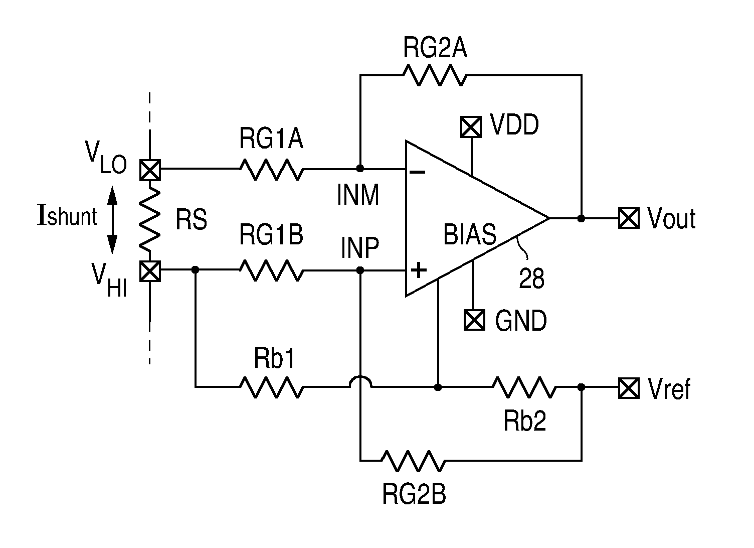
[0025]Referring again to the drawings, FIG. 4 shows a circuit topology in accordance with one aspect of the present invention, including a current sense amplifier 28 and associated external resistor components. FIG. 5 is a schematic diagram of the input stages and second stage of amplifier 28, with FIG. 8 showing a schematic diagram of the output stage. The exemplary circuit is suitable for use in a typical current sensing application where the current amplifier 28 is powered by a supply voltage Vdd ranging from +3.3V to +5V. The amplifier configuration has the ability to safely sense a current signal having a common mode voltage swing with an absolute value higher than the supply voltage Vdd (+12 V for example) or lower than the circuit common Gnd (−12 V for example).

[0026]The circuit topology includes input resistors RG1A and RG1B having respective outer terminals connected to the opposite terminals of the current shunt resistor Rs, namely nodes VLO and VHI. The inner terminals of...


PUM


Abstract

An amplifier configuration including first and second amplifier inputs and a bias input adapted to receive a common mode signal indicative of a common mode input voltage. First and second amplifier input stage sections, each having first and second inputs coupled to respective ones of the first and second amplifier inputs, are provided. Operating mode circuitry switches the amplifier configuration between first and second operating modes in response to the common mode signal, where in the first operating mode the first and second amplifier input stage sections are active and inactive, respectfully and where in the second operating mode the first and second amplifier input stage sections are inactive and active, respectfully. The active first and second amplifier input stage sections are capable of operating with common mode voltages in excess of the upper and lower power supply rails, respectively.

Description

BACKGROUND OF THE INVENTION[0001]1. Field of the Invention[0002]The present invention relates generally to amplifiers and in particular to amplifier configurations capable of amplifying differential signals having associated common mode input voltages which exceed both the upper and lower power supply rails[0003]2. Description of Related Art[0004]Referring to the drawings, FIG. 1A is a simplified diagram of a common type of input stage of a differential amplifier. The input stage includes a pair of NPN transistors 10A / 10B having their respective emitters connected to a common tail current source 12. A pair of load resistors RL1 and RL2 are connected intermediate the respective collector electrodes of the transistors and the upper supply rail Vdd. The input to the amplifier stage is a differential signal Vd, applied between the base electrodes of the transistors, and an associated common mode signal Vcm. The amplifier ideally amplifies the differential signal Vd and does not respond ...

Claims


Application Information

Patent Timeline
Patent Type & Authority Applications(United States)
IPC IPC(8): H03F3/45
CPCH03F3/3022H03F3/4508H03F3/45085H03F2203/45528H03F3/45475H03F2203/45364H03F3/45112
Inventor DANIONI, ALBERTO
Owner TEXAS INSTR INC
Why Eureka
Try Eureka