Differential interference contrast serial time encoded amplified microscopy

a technology of contrast and serial time, applied in the field of optical imaging devices and methods, can solve the problems of constructive/deconstructive interference of wavelength components, and achieve the effect of revolutionizing blood analysis

Active Publication Date: 2013-05-30
RGT UNIV OF CALIFORNIA
View PDF3 Cites 9 Cited by
  • Summary
  • Abstract
  • Description
  • Claims
  • Application Information

AI Technical Summary

Benefits of technology

[0015]The present invention is directed to methods and apparatus for high-speed high-contrast imaging of transparent media without the need for chemical staining that is suitable for a broad range of applications from semiconductor process monitoring to blood screening. The methods and apparatus build on a unique combination of serial time-encoded amplified microscopy (STEAM) an

Problems solved by technology

In other words, the optical path difference between the two adjacent points (illuminated by each wavelength co

Method used


Image

  • Differential interference contrast serial time encoded amplified microscopy
  • Differential interference contrast serial time encoded amplified microscopy
  • Differential interference contrast serial time encoded amplified microscopy

Examples


example 1

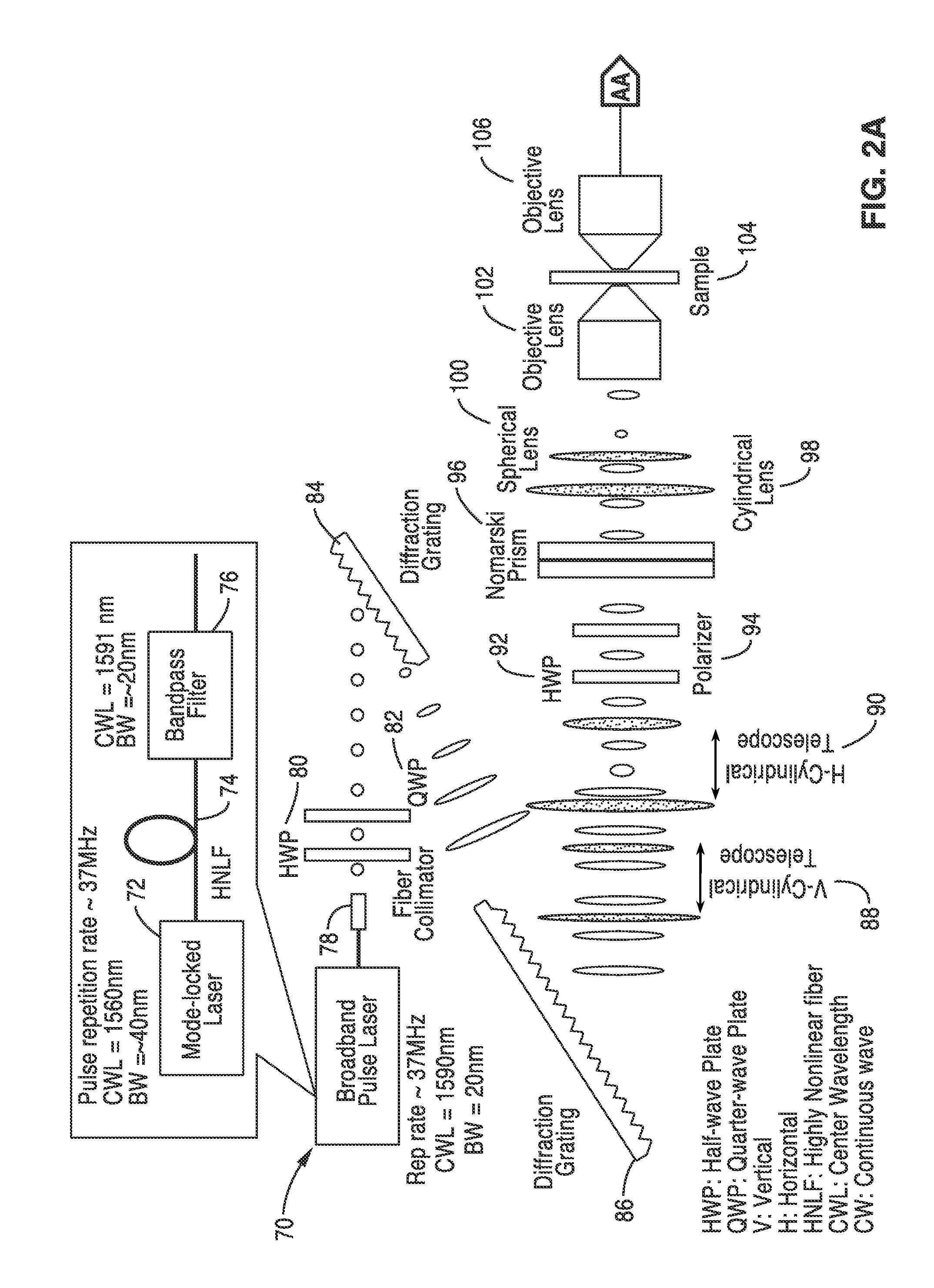
[0058]In order to prove the concepts of the invention, a computer model was created for the system described schematically in FIG. 2A and FIG. 2B that used a crenated sample with a 30 μm width to test the system. The model specimen was meant as a crude example of a typical application such as identification of a certain type of diseased cells. In this simulation, the resolution is assumed to be 0.5 micron and the two adjacent points are 0.2 μm apart. These are typical numbers for a conventional DIC microscope.

[0059]The model of FIG. 2A and FIG. 2B was used and a broadband pulse laser was adopted to generate the probe beam. The beam was mapped into space using a spatial-disperser such as diffraction grating or prism. The spatially-dispersed beam was split into two beams with orthogonal polarization states using a Nomarski / Wollaston prism. The two beams were focused on the sample such that every two adjacent points were illuminated by a certain wavelength but with two different polari...

example 2

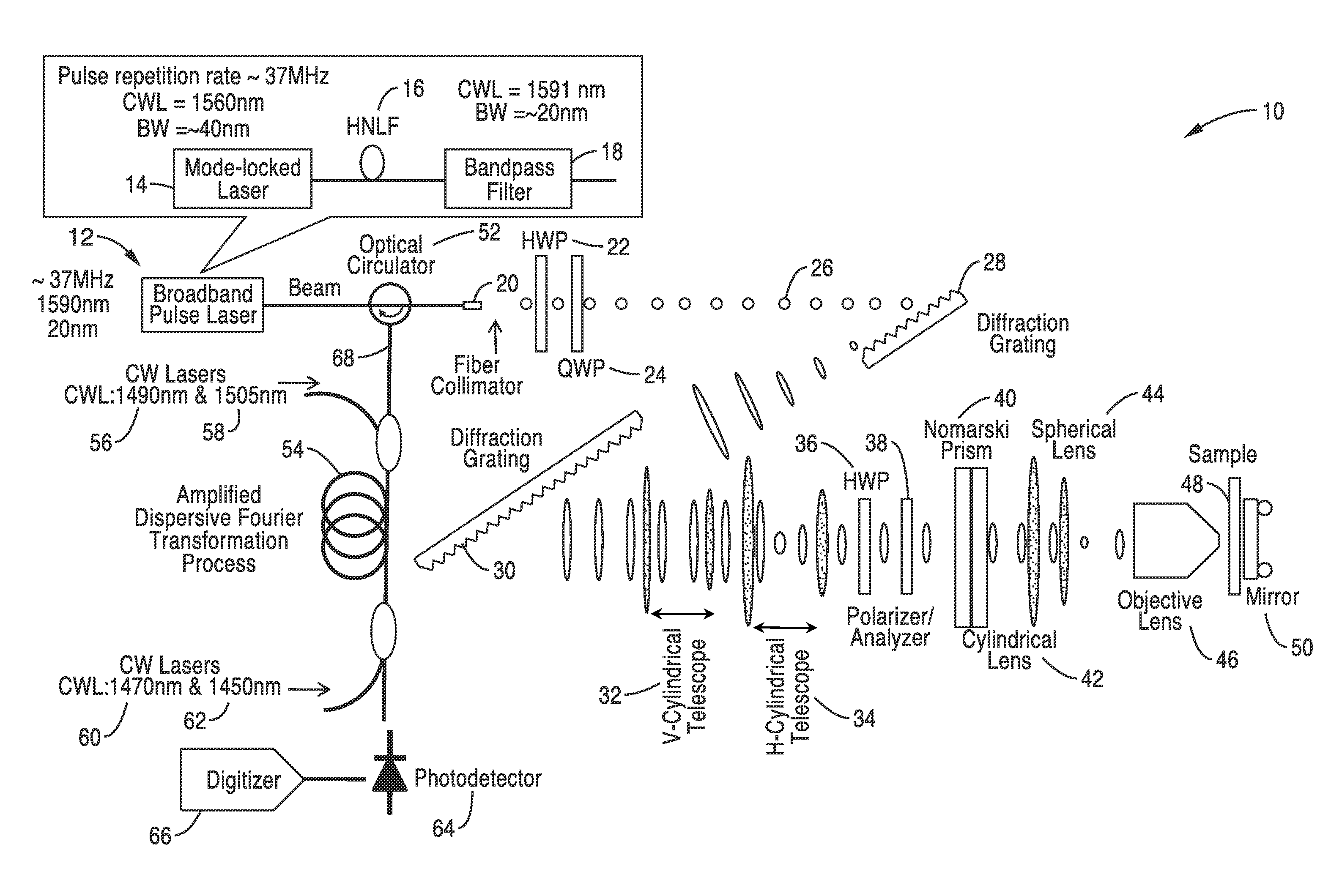
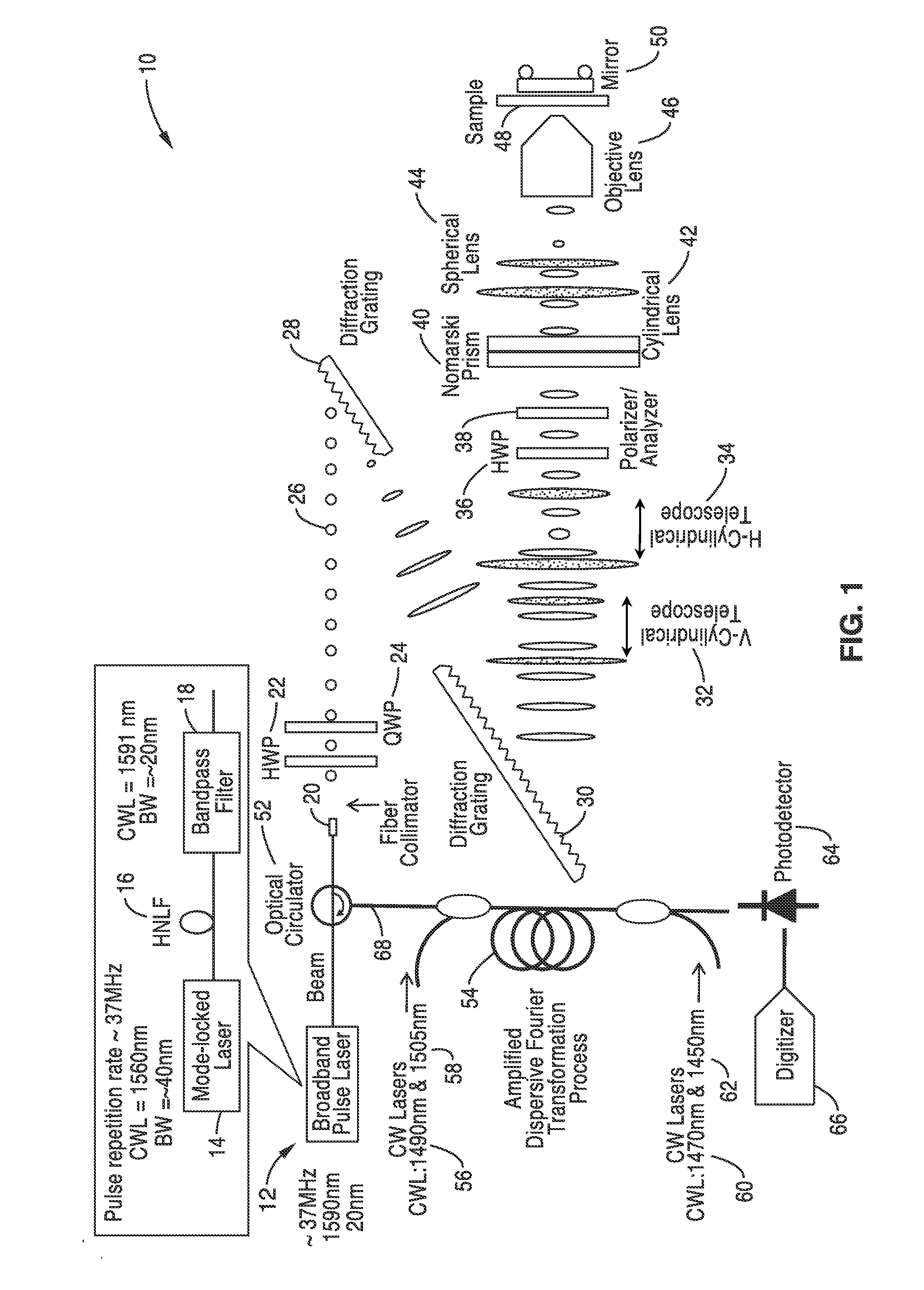
[0065]In order to illustrate the methods for fabrication and the functionality of the differential interference contrast serial time encoded amplified microscopy system, an imager apparatus was constructed according the general schematic shown in FIG. 1. Both one dimensional and two dimensional images of a sample were obtained. The second dimension of the images was obtained by translating the sample in the direction orthogonal to that of the line scans. The sample was a transparent material with periodically refractive-index modulation (i.e. a transmission grating with groove density of ˜70 lines / mm).

[0066]The optical source was a mode-locked laser with a center wavelength of 1560 nm and a pulse repetition rate of 36.1 MHz. A highly nonlinear fiber and optical band-pass filter following the laser produced a train of pulses with ˜20 nm bandwidth centered at 1591 nm was used as an illumination beam.

[0067]Using a pair of diffraction gratings with 1100 lines / mm groove density, the puls...

example 3

[0070]In order to further demonstrate the functionality of the methods and imager, the apparatus shown in FIG. 1 was constructed and used for high-speed, high-contrast imaging of fast-flowing unstained white blood cells. White blood cells were isolated from whole blood by hypotonic lysis of red blood cells and re-suspended in phosphate buffered saline.

[0071]The optical source that was used was a mode-locked laser with a center wavelength of 1560 nm and a pulse repetition rate of 36.1 MHz. A highly nonlinear fiber and optical band-pass filter following the laser produces a train of pulses with ˜20 nm bandwidth centered at 1591 nm as an illumination beam. Using a pair of diffraction gratings with 1100 lines / mm groove density, the pulses were spatially-dispersed into a 1D rainbow pattern enabling 1D line-scanning of the object. The 1D spatially-dispersed (i.e., 1D rainbow) were sent to a half-wave plate and a polarizer to rotate the polarization state of the light and to ensure a 45-de...


PUM


Abstract

We describe methods and apparatus for high-speed high-contrast imaging one-, two- and three-dimensional imaging enabled by differential interference contrast time encoded amplified microscopy of transparent media without the need for chemical staining, that are suitable for a broad range of applications from semiconductor process monitoring to blood screening. Our methods and apparatus build on a unique combination of serial time-encoded amplified microscopy (STEAM) and differential interference contrast (DIC) microscopy. These methods and apparatus are ideally suited for identification of rare diseased cells in a large population of healthy cells and have the potential to revolutionize blood analysis and pathology including identification of cancer cells, such as Circulating Tumor Cells (CTC) in early stage disease.

Description

CROSS-REFERENCE TO RELATED APPLICATIONS[0001]This application is a 35 U.S.C. §111(a) continuation of PCT international application number PCT / US2011 / 041283 filed on Jun. 21, 2011, incorporated herein by reference in its entirety, which is a nonprovisional of U.S. provisional patent application Ser. No. 61 / 357,042 filed on Jun. 21, 2010, incorporated herein by reference in its entirety. Priority is claimed to each of the foregoing applications.[0002]The above-referenced PCT international application was published as PCT International Publication No. WO 2012 / 039802 on Mar. 29, 2012 and republished on May 31, 2012, and is incorporated herein by reference in its entirety.STATEMENT REGARDING FEDERALLY SPONSORED RESEARCH OR DEVELOPMENT[0003]This invention was made with Government support under Grant Number W911 NF-10-1-0006 awarded by US Army Research Office. The Government has certain rights in the invention.INCORPORATION-BY-REFERENCE OF MATERIAL SUBMITTED ON A COMPACT DISC[0004]Not Appl...

Claims


Application Information

Patent Timeline
IPC IPC(8): G01J1/04H04N5/14
CPCG02B21/002H04N5/14G01J1/0411G02B21/14
Inventor JALALI, BAHRAMMOTAFAKKER, ALI
Owner RGT UNIV OF CALIFORNIA
Why Eureka
Try Eureka