Harmonic current suppression method and harmonic current suppression device of power conversion device

a power conversion device and harmonic current suppression technology, applied in the direction of harmonic reduction arrangement, power conversion system, harmonic reduction/ripple reduction, etc., can solve the problems of resistance loss, degraded harmonic suppression function of filter, and inability to conform to this situation, so as to prevent the control from getting unstable, stable harmonic suppression, and suppress the harmonic current flowing

Inactive Publication Date: 2013-05-30
MEIDENSHA ELECTRIC MFG CO LTD
View PDF5 Cites 35 Cited by
  • Summary
  • Abstract
  • Description
  • Claims
  • Application Information

AI Technical Summary

Benefits of technology

[0050](1) According to the invention claimed in claims 1-5, 8-15, 18-20, it is possible to suppress the harmonic current flowing out from the power conversion device due to resonance between the AC filter and the system impedance.
[0051]Moreover, also in cases where the AC filter and the system impedance are unknown and there are many resonance points, it is possible to perform a stable harmonic suppression based on measurement of coefficients by test operation, wherein it becomes unnecessary to design control parameters.
[0052]If variation occurring in the system condition is small, it is possible to continue the stable harmonic suppression where it is unnecessary to change the coefficient. Even when a significant variation occurs in the system condition, it is possible to conform to the variation only by measuring the coefficient again by test operation.
[0053](2) According to the invention claimed in claims 6, 7, 16, 17, it is possible to automatically correct the coefficient that is the inverse function of the transfer characteristic from the harmonic suppression current command value to the AC filter output current measured value.
[0054]It is possible to perform a harmonic suppression following the change of the system condition while preventing the control from getting unstable due to change of the system condition such as load change. It is unnecessary to determine the coefficient by test operation, because it is possible to set the coefficient to a suitable value even if the initial value of the coefficient is not determined carefully.
[0055](3) According to the invention claimed in claims 2, 12, it is possible to suppress harmonic currents even when the harmonic current flowing out from the power conversion device has a plurality of orders.

Problems solved by technology

The method of adding a resistance to a filter capacitor in series is confronted by a problem that the harmonic suppression function of the filter is degraded and the resistance causes a loss.
When variation of the system condition causes a variation in frequency of the harmonic current, it is impossible to conform to this situation, and it is necessary to redesign the parameters.
However, it is difficult to investigate all of circuit constants in the system.
Moreover, filter design is difficult, when harmonics have a plurality of frequencies.
The method disclosed in patent document 2 is confronted by a problem that the method does not take account of the transfer characteristic about amplitude.
Accordingly, if the system condition varies, it is possible that when a harmonic current to be compensated is outputted from an inverter, a major part thereof flows into the filter capacitor, thus causing a problem that the inverter output current for compensating the distortion of the filter current becomes insufficient, so that the distortion remains or compensation for the distortion requires a long time period.
Moreover, it is possible that the filter capacitor and the system cause resonance.
In such a case, the filter current is greater than the inverter output current, so that the compensation for distortion may overshoot to make the control unstable.
Moreover, when variation of the system condition causes a phase offset to deviate from a suitable value, wherein the phase offset is used for inverse dq transformation, a problem occurs where it takes much time to compensate the distortion, or the control becomes unstable.

Method used


Image

  • Harmonic current suppression method and harmonic current suppression device of power conversion device
  • Harmonic current suppression method and harmonic current suppression device of power conversion device
  • Harmonic current suppression method and harmonic current suppression device of power conversion device

Examples


embodiment 1

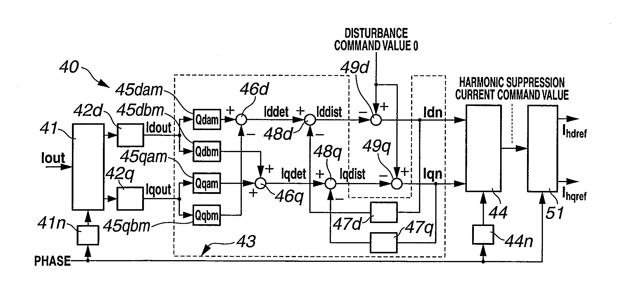
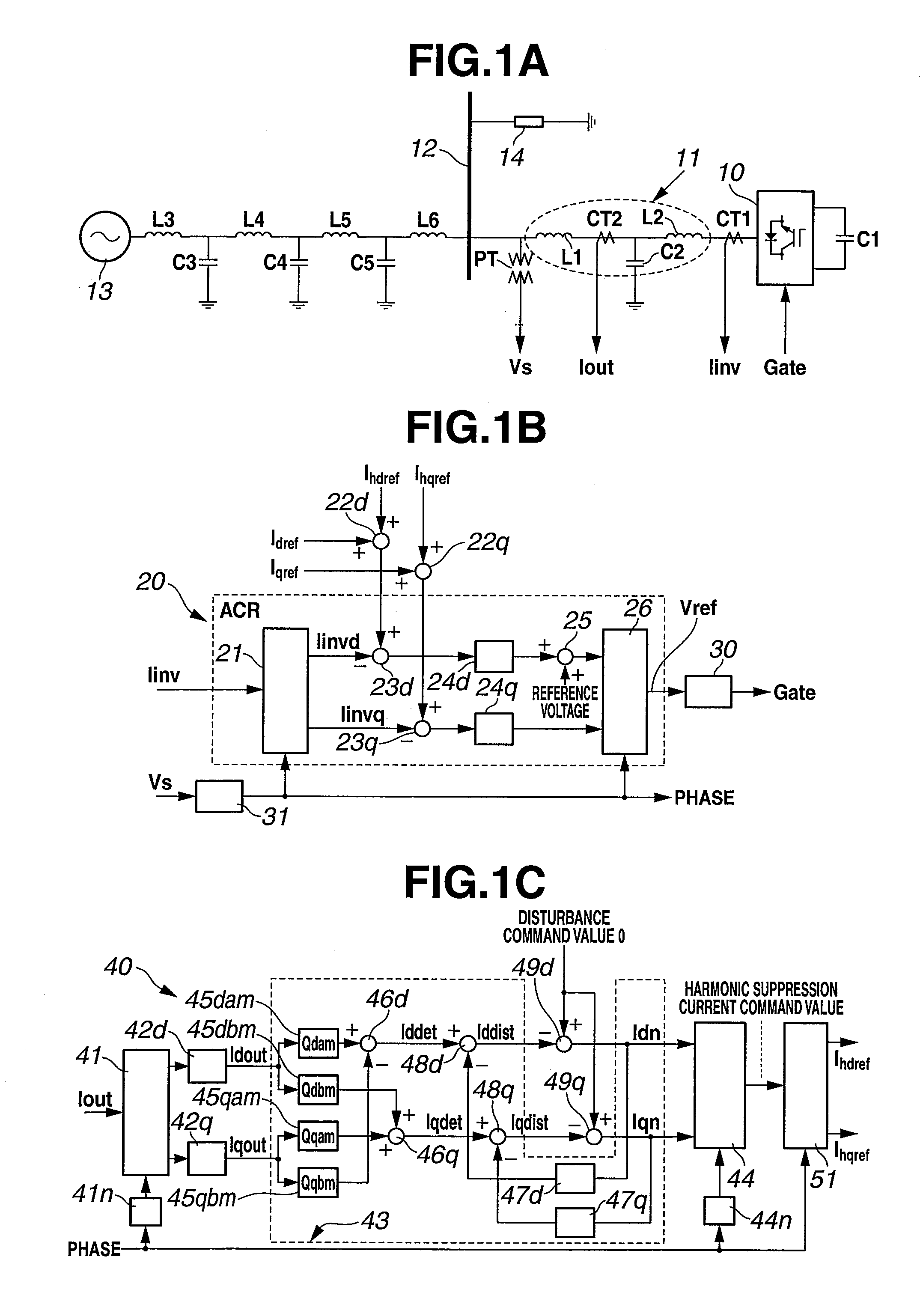
[0083]FIG. 1 shows configuration of a power conversion device 10 according to a first embodiment of the present invention, wherein FIG. 1A shows a main circuit of power conversion device 10, FIG. 1B shows a current control section for controlling the power conversion device 10, and FIG. 1C shows a harmonic suppression control section for controlling the power conversion device 10.

[0084]In FIG. 1A, power conversion device 10 includes an inverter in which an antiparallel unit of a semiconductor switching element and a diode is three-phase-bridge-connected. The direct current side of the inverter is connected to a capacitor C1. The electric energy stored in capacitor C1 is converted into an alternating current by power conversion device 10 and then supplied to a system. The alternating current side of power conversion device 10 is connected to a system bus bar 12 through an LCL filter (AC filter) 11 that is composed of reactors L1, L2 and a capacitor C2. Many devices such as reactors L...

embodiment 2

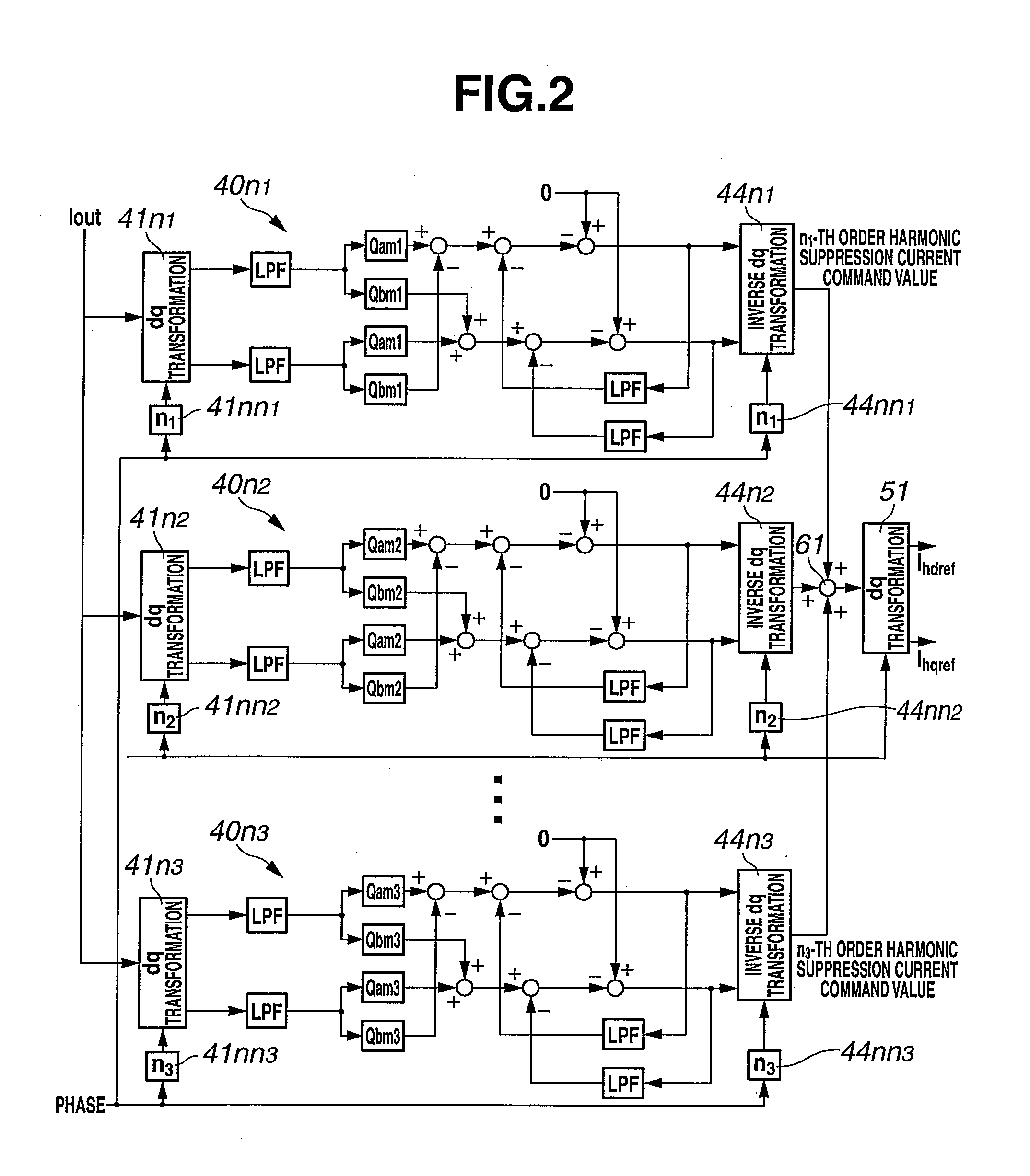
[0140]FIG. 2 shows configuration of a harmonic suppression control section according to a second embodiment. The second embodiment is adapted to suppression of a plurality of orders of harmonics. The harmonic suppression control section shown in FIG. 1C is provided for each of a plurality of orders of harmonics. The other part is configured in the same manner as in the first embodiment.

[0141]In FIG. 2, three harmonic suppression control sections 40n1-40n3 are configured as in FIG. 1C, and output n1-th to n3-th order harmonic suppression current command values which are summed at an adder 61, and dq transformed by dq transformation part 51 to obtain harmonic suppression current command values Ihdref, Ihqref, which are inputted into the current control section of FIG. 1B.

[0142]Reference signs are omitted from the figure for parts of harmonic suppression control sections 40n1-40n3.

[0143]In the second embodiment, the harmonic suppression current command value of each order after inverse...

embodiment 3

[0144]FIG. 3 shows configuration of a third embodiment. The third embodiment is configured by addition of a dq transformation part 71, square calculators 72d, 72q, an adder 73, and tables 74a, 74b. The dq transformation part 71 inputs load current Iload into the harmonic suppression control section of the first embodiment (harmonic suppression control section 40 in FIG. 1C). Square calculators 72d, 72q receive input of d-axis load current Idload and q-axis load current Iqload after conversion of dq transformation part 71, respectively, and calculate a square of d-axis load current Idload and a square of q-axis load current Iqload. Adder 73 sums the square values Idload2 and Iqload2 which are outputted by square calculators 72d, 72q. Tables 74a, 74b calculate coefficients Qa and Qb from coefficients Qam, Qbm which has been proactively measured with respect to variation of load, based on the square value Idload2+Iqload2 which is outputted by adder 73.

[0145]Tables 74a, 74b provide Qam,...


PUM


Abstract

A current control unit takes a deviation between a current command value and a current flowing through an inverter of a power conversion device, and controls the inverter based on the deviation. A harmonic sensing part receives input of an output current of an AC filter, and outputs a predetermined order harmonic of the input current in a direct current value form. A disturbance observer estimates the disturbance of the harmonic based on the output current and a coefficient defined as an inverse function of a transfer function from harmonic suppression current command value to filter output current detection value. A harmonic suppression control unit takes the deviation between the estimated harmonic disturbance and a disturbance command value that suppresses the disturbance, and calculates a harmonic suppression current command value. The harmonic suppression current command value is superimposed on the current command value of the current control unit.

Description

TECHNICAL FIELD[0001]The present invention relates to harmonic current suppression for a power conversion device connected to a system, and relates to a harmonic current suppression device and a harmonic current suppression method capable of following a harmonic suppression control only with test operation wherein it is unnecessary to redesign control parameters irrespective of variation of a condition of the system.BACKGROUND ART[0002]When connected to a system, a power conversion device outputs harmonic currents in addition to a fundamental frequency current. The harmonic currents may cause overheating and breakdown of a power-factor-improving capacitor, burning of a transformer, beat of an electric motor, or malfunctioning of a breaker, wherein the power-factor-improving capacitor, the transformer, the electric motor, and the breaker are connected to the system. Accordingly, a regulation is provided for harmonic outflow when a power conversion device is connected to a system. In ...

Claims


Application Information

Patent Timeline
Patent Type & Authority Applications(United States)
IPC IPC(8): H02M1/12
CPCH02J3/01Y02E40/40H02M1/126H02M7/797H02M1/12H02M7/44H02M7/48
Inventor OI, KAZUNOBUTADANO, YUGO
Owner MEIDENSHA ELECTRIC MFG CO LTD
Why Eureka
Try Eureka