Radiographic image detector and controlling method therefor

a technology of radiographic image and detector, applied in the field of radiographic image detector, can solve the problems of aec processing, certain delay in deciding the time to stop x-ray radiation or in detecting the start or end of x-ray, and is not suitable for parallel input and output of voltage signals

Active Publication Date: 2013-05-30
FUJIFILM CORP
View PDF32 Cites 37 Cited by
  • Summary
  • Abstract
  • Description
  • Claims
  • Application Information

AI Technical Summary

Benefits of technology

[0038]The controller cuts the length of the secondary cycle shorter than the primary cycle by controlling the numbers or intervals of operation control signals applied to the signal processing circuit.

Problems solved by technology

Accordingly, if there is merely one buffer memory in the signal processing circuit, it is impossible to make the pipeline processing or parallel input and output of the voltage signals.
In a radiography system in which the dose detection signal is acquired through signal lines for ordinary pixels and a signal processing circuit for image signals, if the signal processing circuit is configured to make the above-described pipeline processing, a problem could occur in relation to the AEC processing.
That is, there would be a certain delay in deciding the time to stop the x-ray radiation or in detecting the start or the end of x-ray radiation.
As a result, the subject could be overexposed, or the delay in operation of the FPD could result an artifact in the consequent x-ray image, degrading the image quality.
This results in a corresponding delay in determining the start of radiation.
With the elongated cycle period Ts, the delay of almost triple the cycle period, due to the pipeline processing, cannot be ignored as a margin of error in the dose detecting operation.
Particularly, when each radiation time is set as short as several micro seconds for the sake of total dose reduction, i.e. minimum exposure to x-rays, the delay of detection causes an unignorable problem.
The above prior arts do not disclose any solution for the above problem in obtaining the dose detection signal from the dose sensor through the pipeline-type signal processing circuit.

Method used


Image

  • Radiographic image detector and controlling method therefor
  • Radiographic image detector and controlling method therefor
  • Radiographic image detector and controlling method therefor

Examples


first embodiment

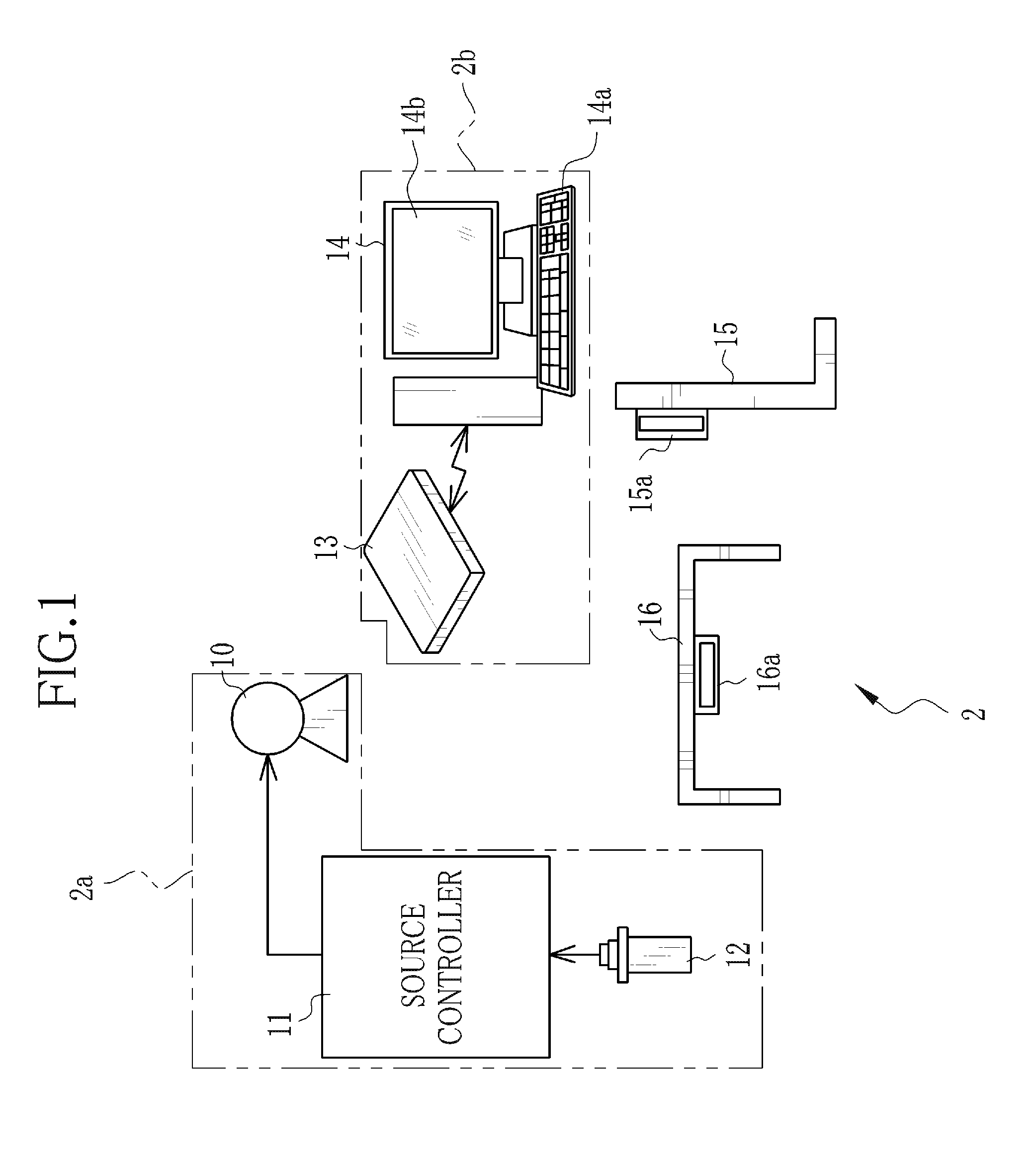
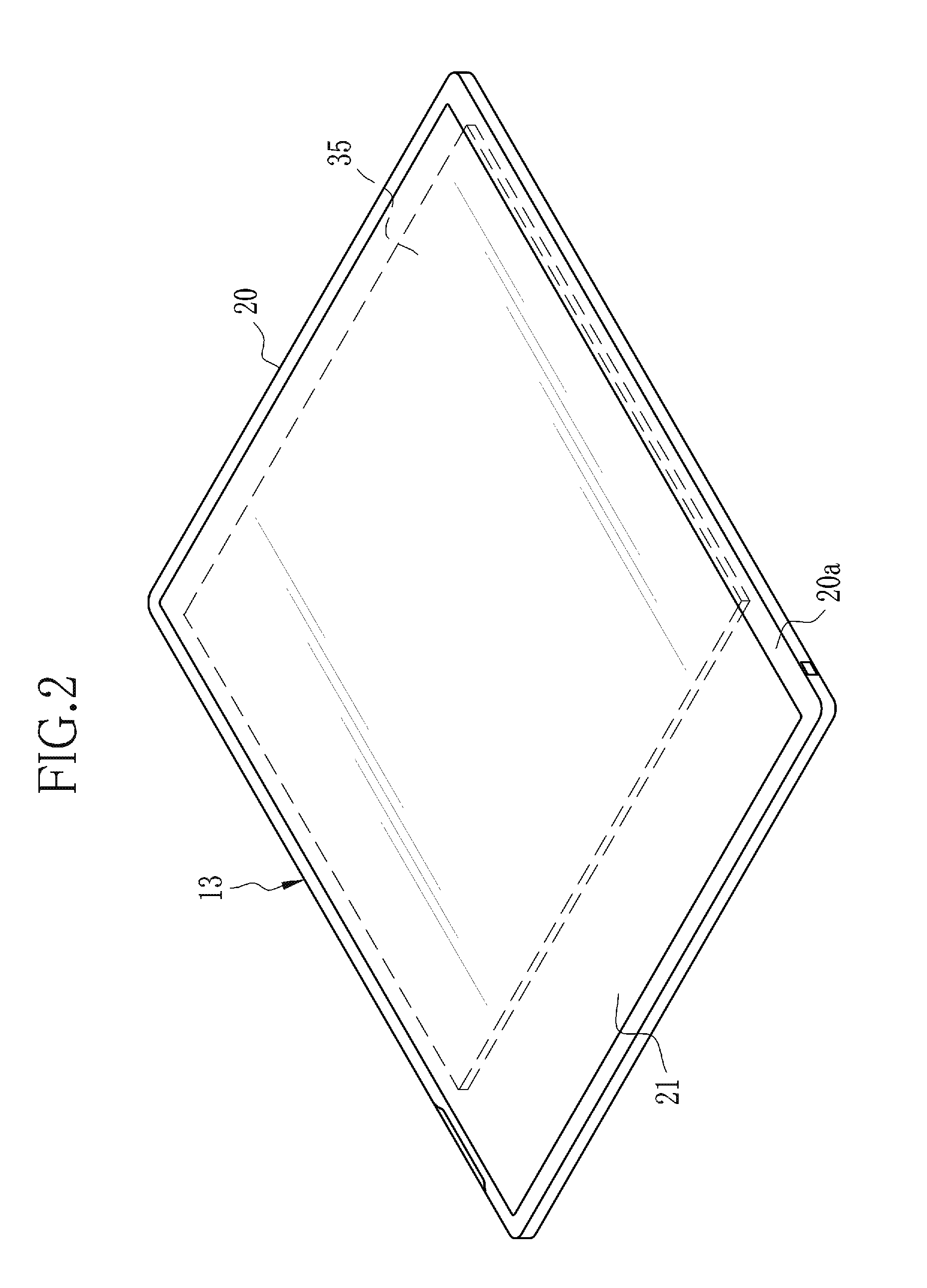
[0063]In FIG. 1, a radiography system 2 includes an x-ray source 10, a source controller unit 11 for controlling the x-ray source 10, an activator switch 12 for instructing a start of radiation from the x-ray source 10, an electronic cassette 13 as a radiographic image detector, a console 14 for controlling operation of the electronic cassette 13 and processing x-ray images acquired through the electronic cassette 13, a radiographic stand 15 for imaging a subject in the standing posture and a radiographic table 16 for imaging a subject lying thereon. The x-ray source 10, the source controller unit 11 and the activator switch 12 constitute an x-ray projector 2a, whereas the electronic cassette 13 and the console 14 constitute an x-ray imaging apparatus 2b. The x-ray projector 2a and the x-ray imaging apparatus 2b are not equipped with any mutual communication device, whereas the electronic cassette 13 has a function to determine the start of radiation from the x-ray projector 2a. The...

second embodiment

[0112]In the above first embodiment, the first and second buffer memories 54a and 54b are provided as the signal holding devices for executing the pipeline processing. Alternatively, as shown in FIG. 6, an FPD 70 may use a signal processing circuit 72, wherein a pair of parallel-connected CDS circuits 71a and 71b is connected to the output of each integrating amplifier 50 individually through an amplifier 55, and the CDS circuit 71a and 71b function as the signal holding devices for pipeline processing.

[0113]The signal processing circuit 72 operates in the manner as shown in FIG. 7 for dose detecting operation. In FIG. 7, “Active CDS” indicates which of the first and second CDS circuits 71a and 71b is sampling and holding the dose detection signal S or the dummy signal D in the current cycle. In this example, the CDS circuits 71a starts sampling and holding the dose detection signal S in a primary cycle, whereas the CDS circuits 71b starts sampling and holding the dummy signal D in ...

third embodiment

[0116]Furthermore, the first and second embodiments may be combined into a third embodiment, as shown in FIG. 8, wherein a signal processing circuit 83 of a flat panel detector (FPD) 80 is provided with first and second CDS circuits 81a and 81b and first and second buffer memories 82a and 82b as signal holding devices. According to this embodiment, the signal processing circuit 83 operates for the dose detecting operation in a manner as shown in FIG. 9.

[0117]In the dose detecting operation, the signal processing circuit 83 repeats the pipeline processing in sets of a primary cycle and following two secondary cycles. In the primary cycle, a dose detection signal S(N) based on those charges s(N) which have been integrated by respective integrating amplifiers 50 in the preceding set are sampled and held in the first CDS circuits 81a (see the timing chart “1st CDS”); a dummy signal D2(N−1), which has been sampled and held in the second CDS circuits 81b in the latter secondary cycle, is ...


PUM


Abstract

A flat panel detector has pixels for obtaining image signals and detective pixels for detecting the amount of incident x-rays. A signal processing circuit is of a pipeline-type, wherein first and second buffer memories are connected to the output of an A / D converter. In a dose detecting operation, the signal processing circuit repeats primary cycles alternately with secondary cycles of a shorter length than the primary cycles. In the primary cycle, a dose detection signal based on electric charges from the detective pixels is input in the first buffer memory and, simultaneously, a dummy signal is output from the second buffer memory. In secondary cycle, the dose detection signal is output from the first buffer memory and, simultaneously, a second dummy signal is input in the second buffer memory. On the basis of the dose detection signals, a start-of-radiation detector detects the start of x-ray radiation.

Description

BACKGROUND OF THE INVENTION[0001]1. Field of the Invention[0002]The present invention relates to a radiographic image detector and a method for controlling the radiographic image detector.[0003]2. Description of the Related Art[0004]In the medical field, radiography systems utilizing radioactive rays, such as x-rays, for imaging are widely known. An x-ray radiography system, an example of radiography systems, includes an x-ray projector for projecting x-rays toward a subject or patient and an x-ray imaging apparatus for acquiring a radiograph or x-ray image of the subject from the x-rays that have penetrated the subject. The x-ray projector includes an x-ray source, a source controller unit for controlling the x-ray source, and an activation switch for inputting a command for actuating the x-ray source to the source controller. The x-ray imaging apparatus includes an x-ray image detector for detecting an x-ray image or x-ray images from incident x-rays, and a console for controlling...

Claims


Application Information

Patent Timeline
Patent Type & Authority Applications(United States)
IPC IPC(8): H05G1/64
CPCH05G1/64G01T1/171A61B6/548H04N5/32
Inventor NOMA, KENTARONAKAMURA, KENJIIWAKIRI, NAOTOKITANO, KOUICHIWATANABE, KEITA
Owner FUJIFILM CORP
Why Eureka
Try Eureka