
Piezoelectric thin film, method for manufacturing same, inkjet head, method for forming image using inkjet head, angular velocity sensor, method for measuring angular velocity using angular velocity sensor, piezoelectric power generation element, and method for generating power using piezoelectric power generation element

Active Publication Date: 2013-05-30
PANASONIC INTELLECTUAL PROPERTY MANAGEMENT CO LTD
View PDF9 Cites 13 Cited by
  • Summary
  • Abstract
  • Description
  • Claims
  • Application Information

AI Technical Summary

Benefits of technology

The present invention relates to a piezoelectric thin film and its manufacturing process, as well as a piezoelectric generating element and its use for generating electric power. The invention provides a piezoelectric generating element that can generate electricity efficiently using a thin film with high piezoelectric properties. The technical effects of this invention are improved performance and reliability of piezoelectric devices, and reduced size and cost of ink jet heads for forming high-quality images. The piezoelectric generating element can also be used for measuring angular velocity and has long-term stability and durability.

Problems solved by technology

PZT, however, contains a large amount of lead.
In recent years, there has been a growing concern that lead leached from waste may cause serious damage to the ecosystem and the environment.

Method used


Image

  • Piezoelectric thin film, method for manufacturing same, inkjet head, method for forming image using inkjet head, angular velocity sensor, method for measuring angular velocity using angular velocity sensor, piezoelectric power generation element, and method for generating power using piezoelectric power generation element
  • Piezoelectric thin film, method for manufacturing same, inkjet head, method for forming image using inkjet head, angular velocity sensor, method for measuring angular velocity using angular velocity sensor, piezoelectric power generation element, and method for generating power using piezoelectric power generation element
  • Piezoelectric thin film, method for manufacturing same, inkjet head, method for forming image using inkjet head, angular velocity sensor, method for measuring angular velocity using angular velocity sensor, piezoelectric power generation element, and method for generating power using piezoelectric power generation element

Examples


example 1

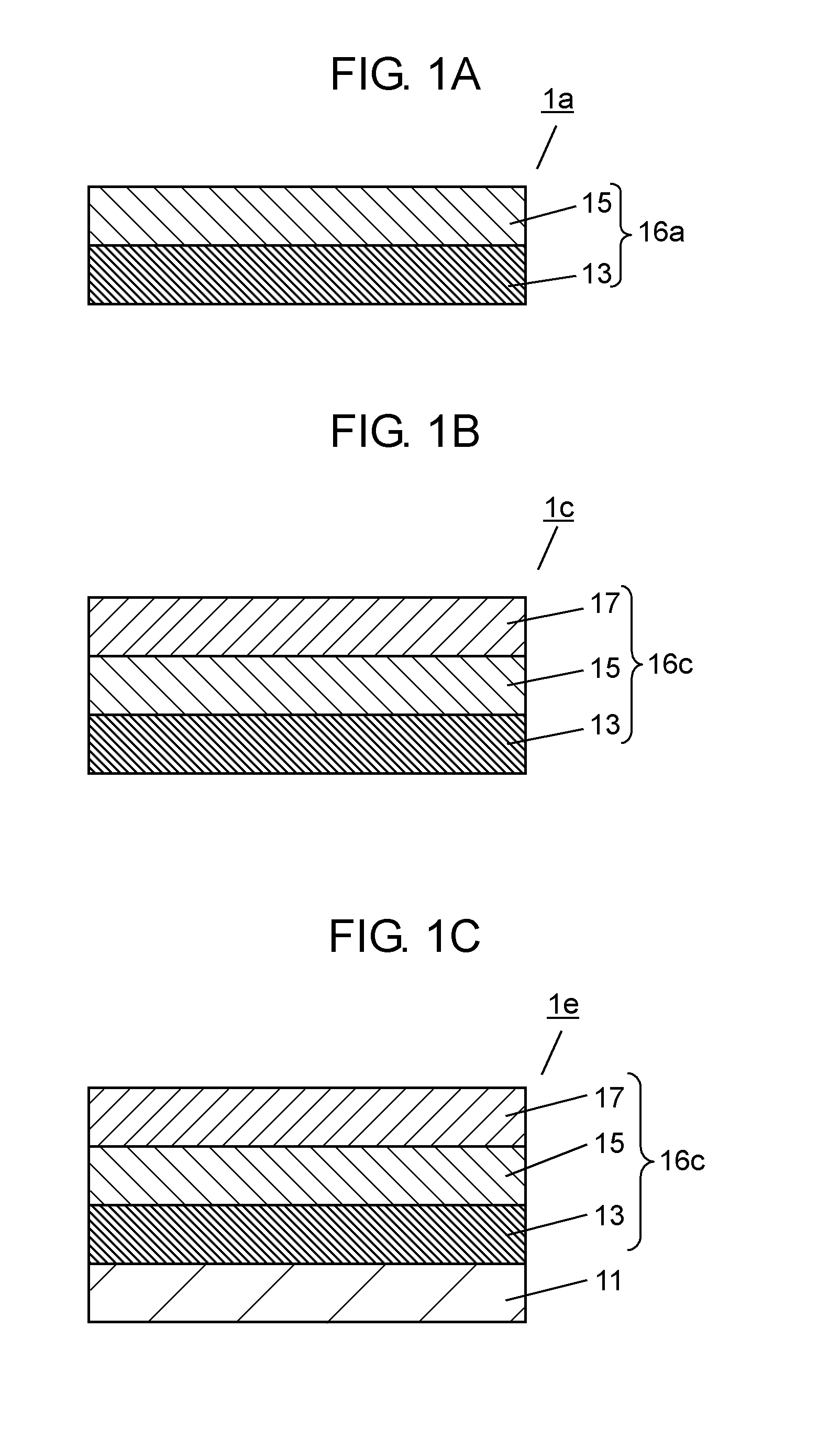
[0240]In this example, a piezoelectric thin film having a structure shown in FIG. 1E was fabricated. The piezoelectric thin film comprises the MgO substrate 11, the Pt electrode film 13, the (Na,Bi)TiO3—BaTiO3 film 15, and the conductive film 17 in this order. The fabrication procedure is as follows.

[0241]A Pt electrode film (with a thickness of 250 nm) having a (110) orientation was formed by RF magnetron sputtering on the MgO surface, having a plane orientation of (110), of a monocrystalline Si substrate. The Pt electrode film corresponds to the electrode film 13. The Pt electrode film was formed using a metallic Pt target in an argon (Ar) gas atmosphere under the film formation conditions of an RF power of 20 W and a substrate temperature of 500 degree Celsius.

[0242]Next, a (1-x)(Na,Bi)TiO3-xBaTiO3 film (with a thickness of 3.0 micrometers, x=0.03) was formed by RF magnetron sputtering on the surface of the Pt electrode film 13. This film corresponds to the (Na,Bi)TiO3—BaTiO3 fil...

example 2

[0250]An identical experiment to that of the example 1 was performed except that x was equal to 0.15.

[0251]As shown in FIG. 17 and Table 1, it was confirmed that the piezoelectric film according to the example 2 had an orthorhombic crystal structure, since it had strong intensity of a (110) reflection peak.

[0252]The piezoelectric constant d31 of the piezoelectric thin film according to the example 2 was −136 pC / N, which was equivalent to the piezoelectric constant d31 of a PZT film.

example 3

[0253]An identical experiment to that of the example 1 was performed except that x was equal to 0.09.

[0254]As shown in FIG. 17 and Table 1, it was confirmed that the piezoelectric film according to the example 3 had an orthorhombic crystal structure, since it had strong intensity of a (110) reflection peak.

[0255]The piezoelectric constant d31 of the piezoelectric thin film according to the example 3 was −175 pC / N, which was equivalent to the piezoelectric constant d31 of a PZT film.


PUM

PropertyMeasurementUnit
Thicknessaaaaaaaaaa
Piezoelectricityaaaaaaaaaa
Ferroelectricityaaaaaaaaaa

Abstract

Provided is a piezoelectric thin film including a non-lead-containing (that is, lead-free) ferroelectric material and having high piezoelectric performance comparable to that of PZT, and a method of manufacturing the piezoelectric thin film. The piezoelectric film according to the present invention comprises a laminate structure. The laminate structure comprises an electric film and a (1-x)(Na,Bi)TiO3-xBaTiO3 film. x represents a value of not less than 0.03 and not more than 0.15. The (1-x)(Na,Bi)TiO3-xBaTiO3 film has a (110) surface orientation only. The (1-x)(Na,Bi)TiO3-xBaTiO3 film has an orthorhombic crystal structure only.

Description

[0001]This is a continuation of International Application No. PCT / JP2011 / 006402, with an international filing date of Nov. 17, 2011, which claims priority of Japanese Patent Application No. 2011-021331, filed on Feb. 3, 2011, the contents of which are hereby incorporated by reference.TECHNICAL FIELD[0002]The present disclosure relates to a piezoelectric thin film including a piezoelectric layer and a method of manufacturing the same. The present invention further relates to an ink jet head including the piezoelectric thin film and a method of forming an image by the head, to an angular velocity sensor including the piezoelectric thin film and a method of measuring an angular velocity by the sensor, and to a piezoelectric generating element including the piezoelectric thin film and a method of generating electric power using the element.BACKGROUND ART[0003]Lead zirconate titanate (PZT: Pb(ZryTi1-y)O3, 0<y<1) is a typical ferroelectric material capable of storing a large amount ...

Claims


Application Information

Patent Timeline
IPC IPC(8): H01L41/18C30B29/32C30B29/68B41J2/14H01L41/113G01C19/5621H01L41/314
CPCB41J2/14233B41J2202/03G01C19/5621H01L41/0973H01L41/1873H01L41/1878H01L41/314C30B29/32C30B29/68H01L41/113H01L41/1132H01L41/183H01L41/0805B41J2/14201H10N30/306H10N30/2047H10N30/8561H10N30/8542H10N30/853H10N30/074H10N30/704H10N30/852H10N30/30H10N30/302
Inventor HARIGAI, TAKAKIYOTANAKA, YOSHIAKIADACHI, HIDEAKIFUJII, EIJI
Owner PANASONIC INTELLECTUAL PROPERTY MANAGEMENT CO LTD
Learn More