Eureka AIR delivers breakthrough ideas for toughest innovation challenges, trusted by R&D personnel around the world.

Physics-based simulation of warhead and directed energy weapons

a technology of directed energy weapons and simulation systems, applied in the field of simulation systems of vehicles, can solve the problems of difficult modeling of high-complex entity interactions with high precision, difficult to model high-speed missiles and their interaction with aircraft targets, etc., and achieve the effect of assessing limited damage short of destruction

Inactive Publication Date: 2013-05-30
L 3 COMM CORP
View PDF27 Cites 26 Cited by
  • Summary
  • Abstract
  • Description
  • Claims
  • Application Information

AI Technical Summary

Benefits of technology

The present invention is about a computerized system and method that can simulate the damage of a vehicle, such as an aircraft, caused by limited damage. The system can also realistically simulate the effects of missiles or directed energy weapons, making it more effective to train in defensive maneuvers against these threats. The technical effect of this invention is to provide a more accurate and realistic training tool for defense against missiles and directed energy weapons.

Problems solved by technology

The interactions of such a simulation may be very complicated and take place at very high speeds.
Modeling such highly-complex entity interactions with high precision is challenging in distributed training simulations, and modeling a high speed missile and its interaction with an aircraft target is particularly difficult.
Missiles and aircraft can close together hundreds of feet in a fraction of a second, which can present a problem even in a purely localized group of simulators, and becomes much more difficult in a more geographically-distributed system where there is also a problem of latency, i.e., communication delays caused by the distance between the simulators and the lag of the interlinking network.
Even with rapid processing frame times and manageable network latencies, an error in position between a missile detonation and the aircraft target is likely to occur in distributed simulations.
Very slight positional errors introduced by latency and jitter can cause missile models to fail.
Even when the distance errors are in the tens of feet, the missile's small warhead and an inexact target aircraft location can produce significant inaccuracies when calculating the effect of detonation effects or the occurrence of weapon impacts.
Also, latency between simulations and jitter may degrade these models in higher-fidelity systems.
This mismatch between systems can lead to confusion as to whether a missile was truly effective or not.
Other systems increase the kill distance of the warhead to compensate for any latency or network issues, sometimes up to thousands of feet, with an obvious loss of accuracy in the simulation.
Significant training issues can arise from these two approaches to missile warhead modeling.
The pilot in a high-fidelity flight simulator might have maneuvered or reacted to a missile effectively, but was nonetheless killed by a bad roll of the dice or a poorly implemented kill decision in the simulation system.
Being on the unlucky side of the roll of the dice that gets one's ownship destroyed often leaves the trainee who was hit by the missile with questions like “why did it kill me?”, “how close was it?”, and “how could I have better survived?” It also becomes impossible to tell the pilot how to improve his counter-missile defensive tactics if the feedback from the results of the engagement appears random.
The difficulty of assessing effectiveness in a simulation of a directed energy weapon, e.g., a laser system, may be even more complex than determining missile effectiveness, due to the even higher speed of the damage delivery and the longer duration of interaction with the target.
These overall difficulties with the prior art simulation systems result in the accuracy of the simulation and fair fight parameters of the training being reduced, and the inability to accurately determine effectiveness of a missile or a directed energy weapon against a target makes training in defensive strategies very difficult or impossible.

Method used


Image

  • Physics-based simulation of warhead and directed energy weapons
  • Physics-based simulation of warhead and directed energy weapons
  • Physics-based simulation of warhead and directed energy weapons

Examples


example

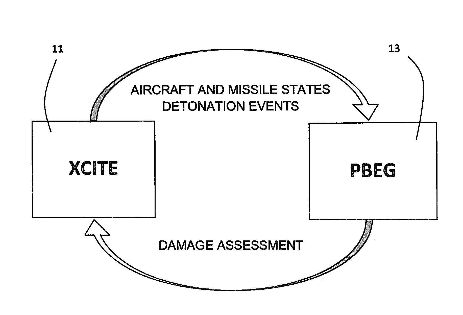
[0225]As seen in FIGS. 22 and 23, the damage of the target plane is superimposed in the visualization in such a way that it becomes immediately apparent what part is being hit and what was previously damaged.

[0226]In the scenario shown in FIG. 24, the MiG-29 took a slight left action preventing the ABL's laser from staying completely on target. Referring to FIG. 23, at the outset of the encounter, the ABL managed to score approximately 5 seconds worth of dwell time on the right engine and heat one piece over 80 degrees. The particular piece that was heated 85 degrees took a total of 3.40 seconds of laser time and is located at in entity coordinates. After striking the right engine for 5 seconds, the laser was forced onto the left engine where it quickly found a spot it could stick on for 17.39 seconds and deliver the threshold amount of heat, 733° K, to destroy that part.

[0227]It is noteworthy that FIG. 22 and FIG. 23 are from different test runs of the system. FIG. 24 is an illus...


PUM


Abstract

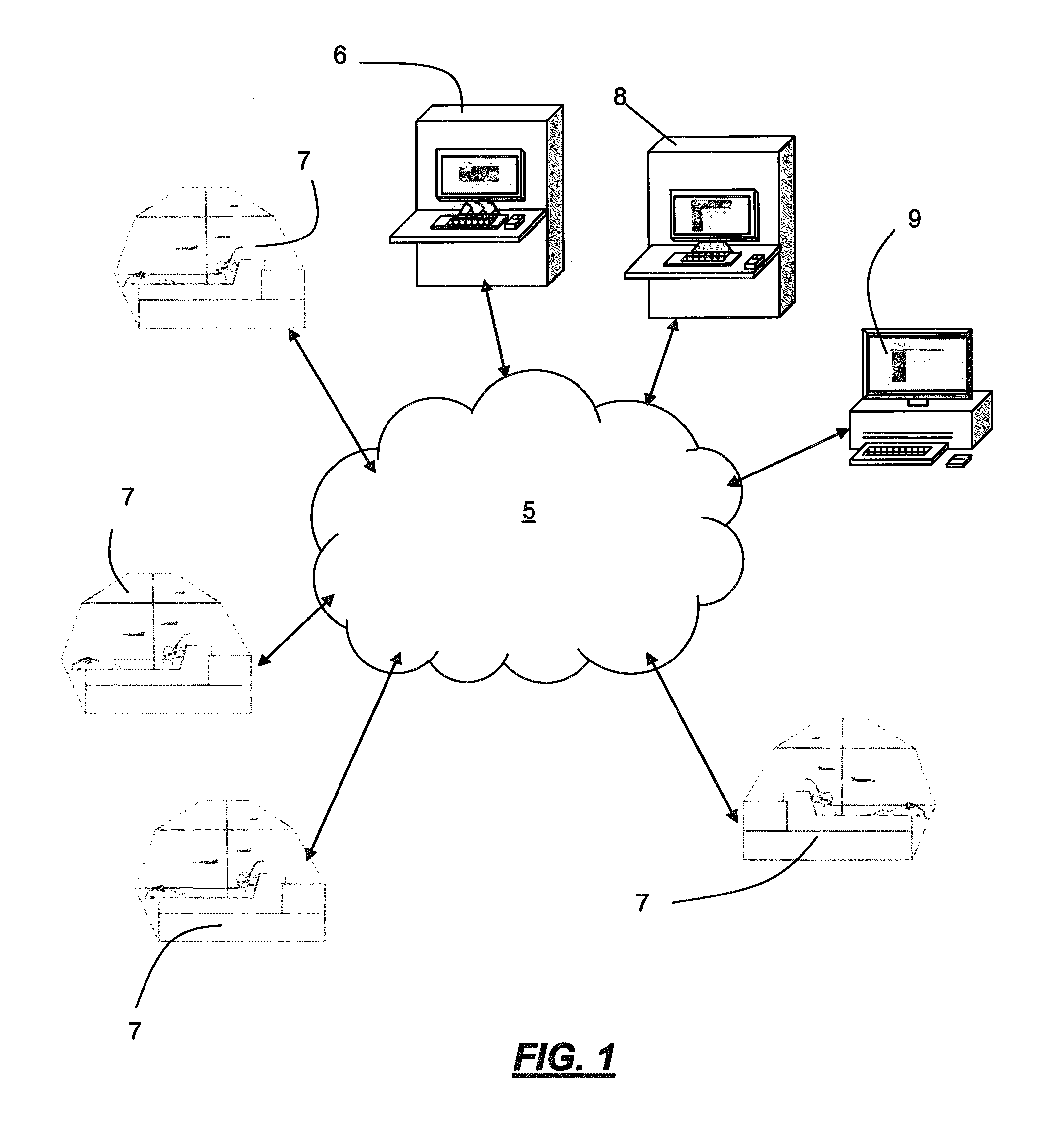
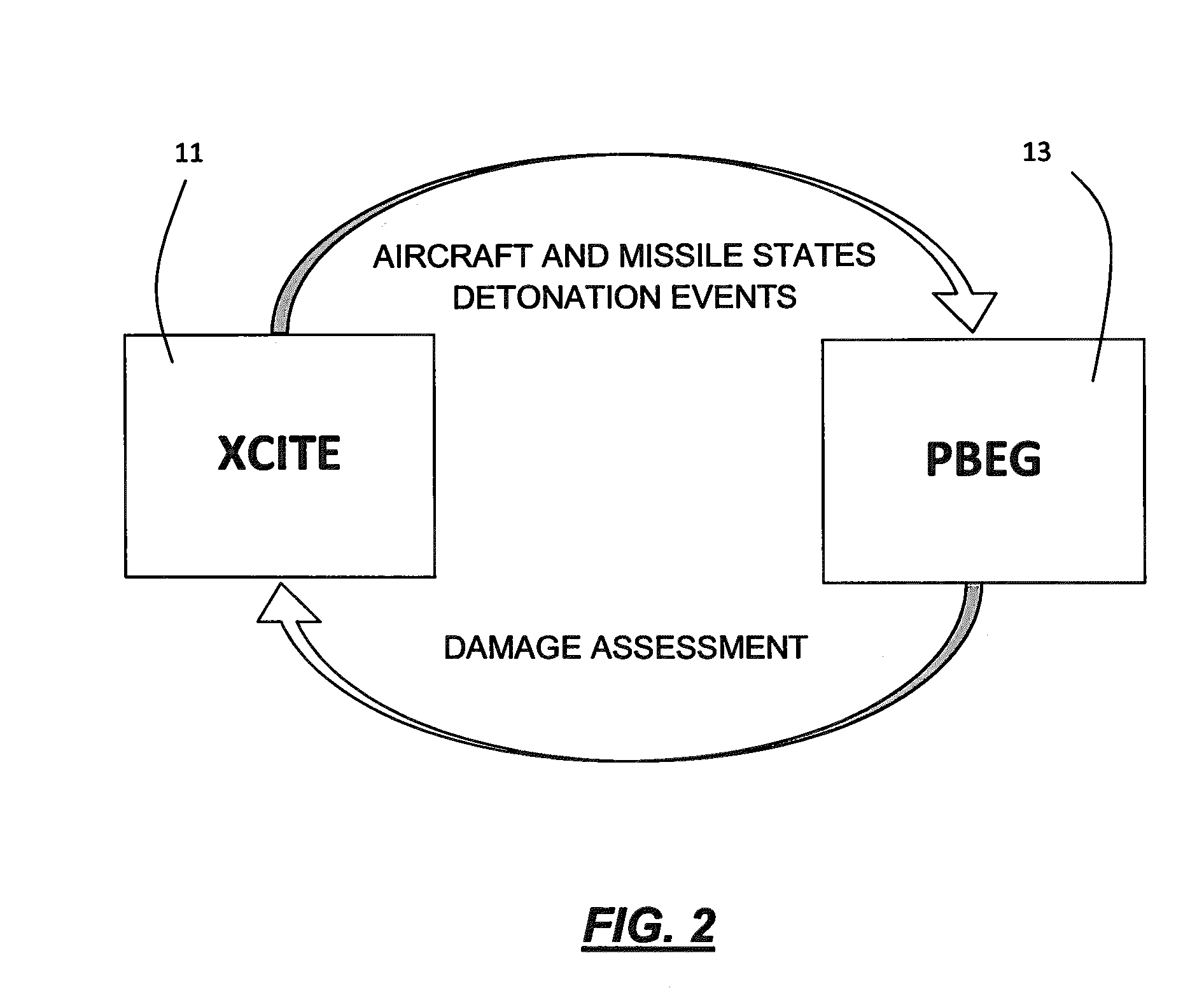
A network connects stations in a distributed physics based simulation system. When the simulation detects that a weapon, especially a missile or directed energy beam, is engaging a target vehicle, one physics station determines damage status of the target vehicle. The detonation or strike of the weapon is applied to a model of the vehicle composed of pieces each made up of a number of parts. Where the damage to a piece of the vehicle exceeds a predetermined threshold, the piece is removed from the vehicle, and where a predetermined maximum damage is reached for the vehicle, the vehicle is considered destroyed. The damage assessment from the weapon is made using raytracing in a physics engine that is also used to control movement of virtual objects in the simulation according to rules of physics of the physics engine.

Description

[0001]This invention was made with government support under USAF CRADA number 03-225-HE-02 awarded by the U.S. Air Force, Air Force Research Laboratory, 711th Human Performance Wing, Human Effectiveness Directorate, Warfighter Readiness Research Division. The government has certain rights in the invention.FIELD OF THE INVENTION[0002]The present invention relates to simulator systems for simulating vehicles, especially aircraft in combat, and more particularly to distributed simulation systems using physics-based environment simulation for combat aircraft.BACKGROUND OF THE INVENTION[0003]Simulation systems are frequently employed to train operators of vehicles, especially pilots of aircraft, in various simulated combat exercises in which a warfare theatre and various forces are modeled. One particularly effective system for providing such simulation to one or more trainees linked by a distributed network is shown in U.S. published patent application 2009 / 0099824 A1 of Falash et al., ...

Claims


Application Information

Patent Timeline
Patent Type & Authority Applications(United States)
IPC IPC(8): G09B9/00
CPCG09B9/003F42B15/10G09B9/08G09B9/085G09B9/24
Inventor POLLAK, EYTANWELLS, JACK CHARLESLAY, MERRILL
Owner L 3 COMM CORP
Why Eureka
Eureka Blog
Learn More