Washing Machine Drive System

a technology for driving systems and washing machines, applied in other washing machines, domestic applications, textiles and paper, etc., can solve the problems of long service life of the drive motor, large volume, complex structure of the drive mechanism, etc., and achieve the effect of reliable performance and simple structur

Inactive Publication Date: 2013-06-06
CHANGZHQU MASTER MACHINERY
View PDF5 Cites 9 Cited by
  • Summary
  • Abstract
  • Description
  • Claims
  • Application Information

AI Technical Summary

Benefits of technology

[0024]The present invention includes the features such as the square-wire spring clutch, the cone-shaped brake, the planetary gear with a rack gear, and the sector shaped output gear outputting positive and negative torque, which has simple structures, reliable driving power transmission, precise braking, less space required, easy installation and maintenance, and a longer service life, exhibiting a higher level of novelty and creativity.

Problems solved by technology

However, such operation may require frequent starting and back-and-forth rotating of the drive motor, which generally leads to a much shorter serving life for the drive motor.
Thus, the structure of the drive mechanism can be complex and often need coordination between clutch and brake modules.
This may result in a bulky and complex structure that may be inconvenient for installation and maintenance.
Further, because the brake module is provided separately, it may be easy to cause coordinating issues between braking and driving operations.
Sometimes the braking operation and the driving operation are performed at the same time or the braking operation is performed after the driving operation stops for a while, which may be undesired during operation.

Method used


Image

  • Washing Machine Drive System
  • Washing Machine Drive System
  • Washing Machine Drive System

Examples


Embodiment Construction

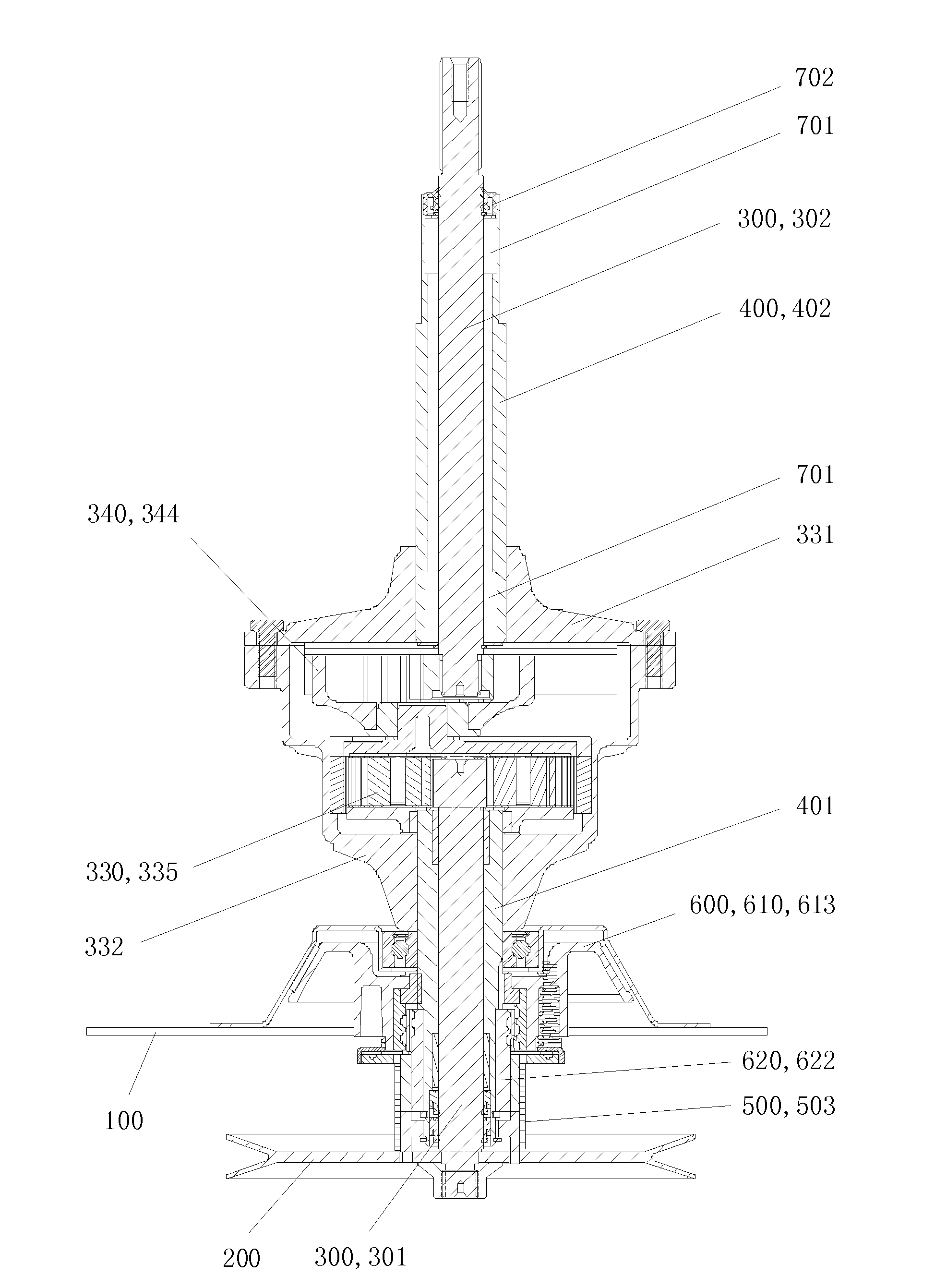
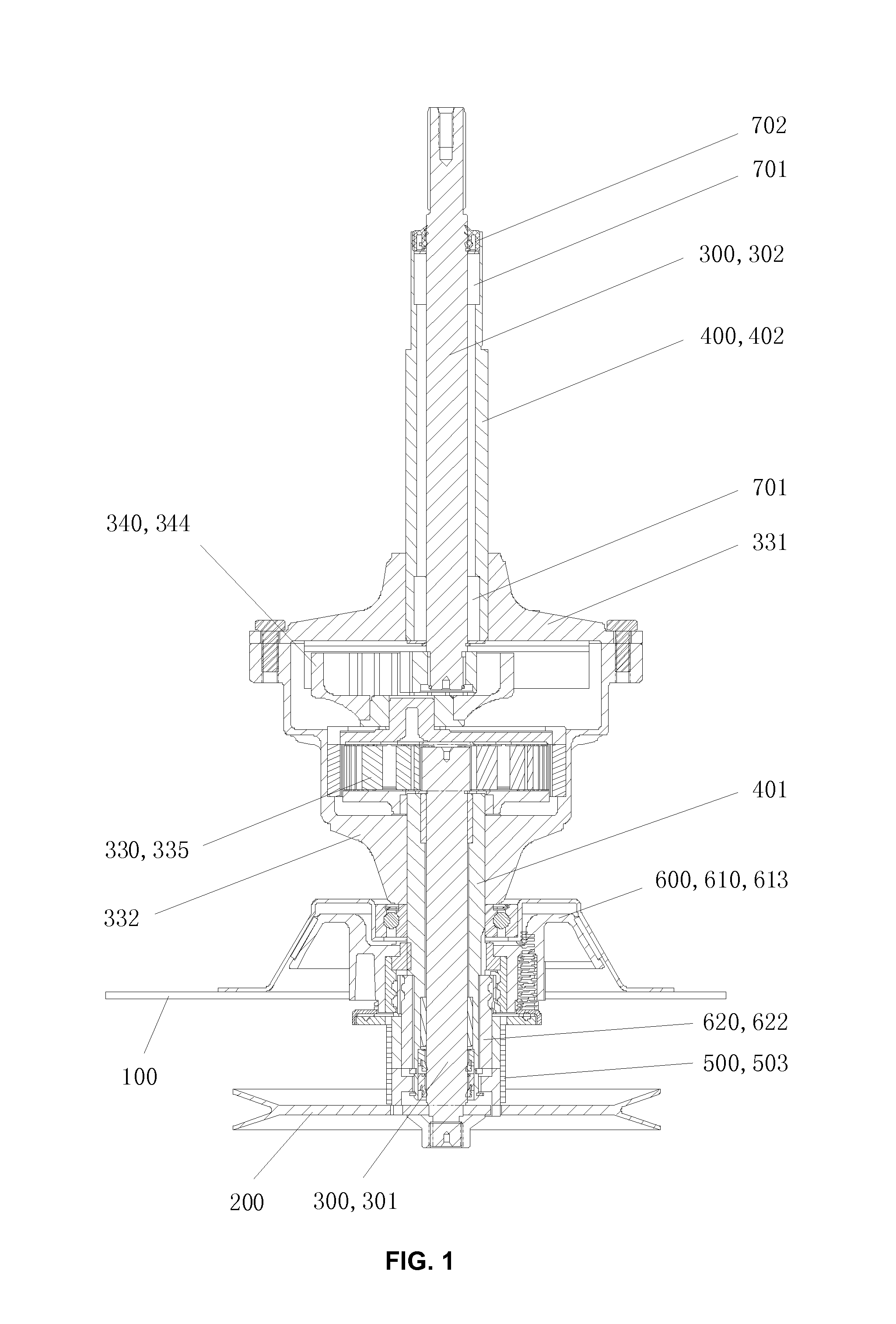
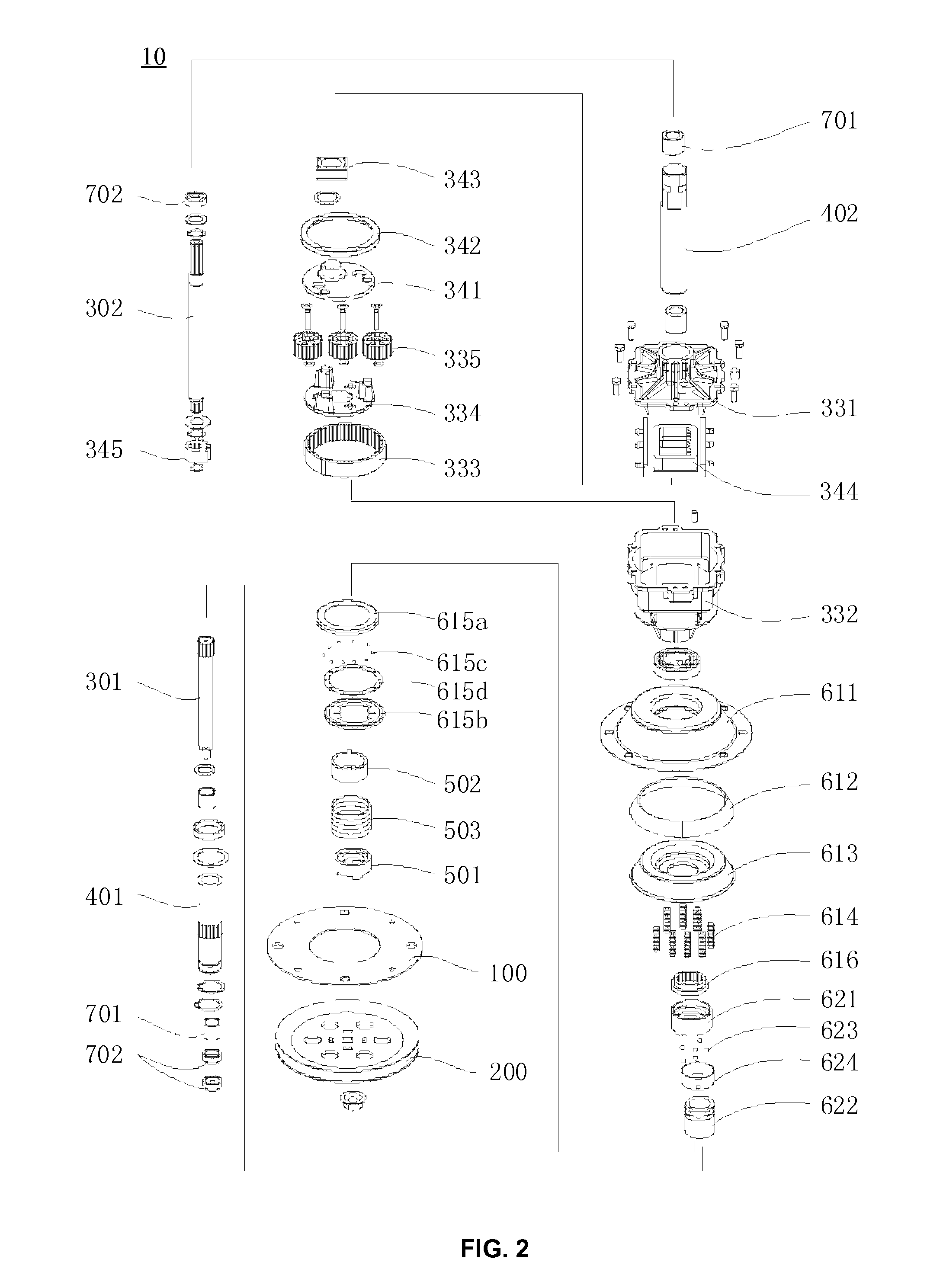
[0037]As shown in FIG. 1-3, the present invention includes a mounting plate 100 connecting to the body of the washer, a driving pulley 200, a main shaft assembly 300, a sleeve shaft assembly 400, a clutch 500, and a brake module 600. The lower part of main shaft assembly 300 is connecting to the driving pulley 200. The sleeve shaft assembly 400 and main shaft assembly 300 are coaxially arranged and can rotate with respect to each other. The lower end of the sleeve shaft assembly 400 is connected with driving pulley 200 through the clutch 500.

[0038]The main shaft assembly 300 includes an input shaft 301 and an output shaft 302. A planetary gear module 330 and an oscillating drive output module 340 are configured between the input shaft 301 and the output shaft 302. The braking module 600 includes a cone-shaped brake unit 610 and a braking control unit 620.

[0039]The brake unit 610 includes a cone flange 611 fastened to the mounting plate 100, a brake pad 612 lining at the inner wall o...


PUM


Abstract

The present invention discloses a top-loading washer drive system. The system includes a mounting plate connecting to the body of the washer, a driving pulley, a main shaft assembly fastened to the washer agitator, a sleeve shaft assembly fastened to the washer basket, a clutch, and a brake module. The lower part of main shaft assembly is connecting to the driving pulley. The sleeve shaft assembly and main shaft assembly are coaxially arranged and can rotate with respect to each other. The lower end of the sleeve shaft assembly is connected with driving pulley through the clutch. The main shaft assembly includes an input shaft at one end and an output shaft at the other end. A planetary gear module and an oscillating drive output module are configured between the input shaft and the output shaft. The braking module includes a cone-shaped brake unit and a braking control unit.

Description

FIELD OF THE INVENTION[0001]The present invention generally relates to drive mechanisms for washing machine and, more particularly, to top-loading washer drive systems.BACKGROUND[0002]Similar to other types of washers, a top-loading washer usually has a washing cycle and a spin cycle. During the washing cycle, the agitator rotates back and forth to achieve washing operation; while during the spin cycle, both the agitator and the basket rotate at a high speed to spin water out of the washing items. By rotating back and forth, the agitator can effect better washing operation and prevent the washing items inside the basket from tangling altogether. The agitator's back and forth rotation operation is realized by changing the rotating directions of a drive motor controlled by a controller. However, such operation may require frequent starting and back-and-forth rotating of the drive motor, which generally leads to a much shorter serving life for the drive motor.[0003]In addition, due to ...

Claims


Application Information

Patent Timeline
Patent Type & Authority Applications(United States)
IPC IPC(8): D06F37/30
CPCD06F37/40D06F37/30D06F13/02
Inventor CHEN, CHANG
Owner CHANGZHQU MASTER MACHINERY
Why Eureka
Try Eureka