Piezoelectric actuator and method for manufacturing same

a technology of piezoelectric actuators and actuators, applied in piezoelectric/electrostrictive transducers, relays, generators/motors, etc., can solve problems such as cantilever warp, and achieve the effect of maintaining stably the internal stress of piezoelectric elements

Inactive Publication Date: 2013-06-06
TAIYO YUDEN KK
View PDF5 Cites 27 Cited by
  • Summary
  • Abstract
  • Description
  • Claims
  • Application Information

AI Technical Summary

Benefits of technology

[0013]In view of the above-mentioned situations, an object of the present invention is to provide a piezoelectric actuator that can stably maintain an internal stress of a piezoelectric element and a method of manufacturing the same.

Problems solved by technology

In such a configuration, relaxation of internal stress of the metal layer occurs due to plastic deformation or creep of the metal layer, which is caused by repetitive motion, and as a result, the stress control amount that was initially set may be changed, causing the cantilever to warp.

Method used


Image

  • Piezoelectric actuator and method for manufacturing same
  • Piezoelectric actuator and method for manufacturing same
  • Piezoelectric actuator and method for manufacturing same

Examples


embodiment 1

[0053](Configuration of Piezoelectric Actuator)

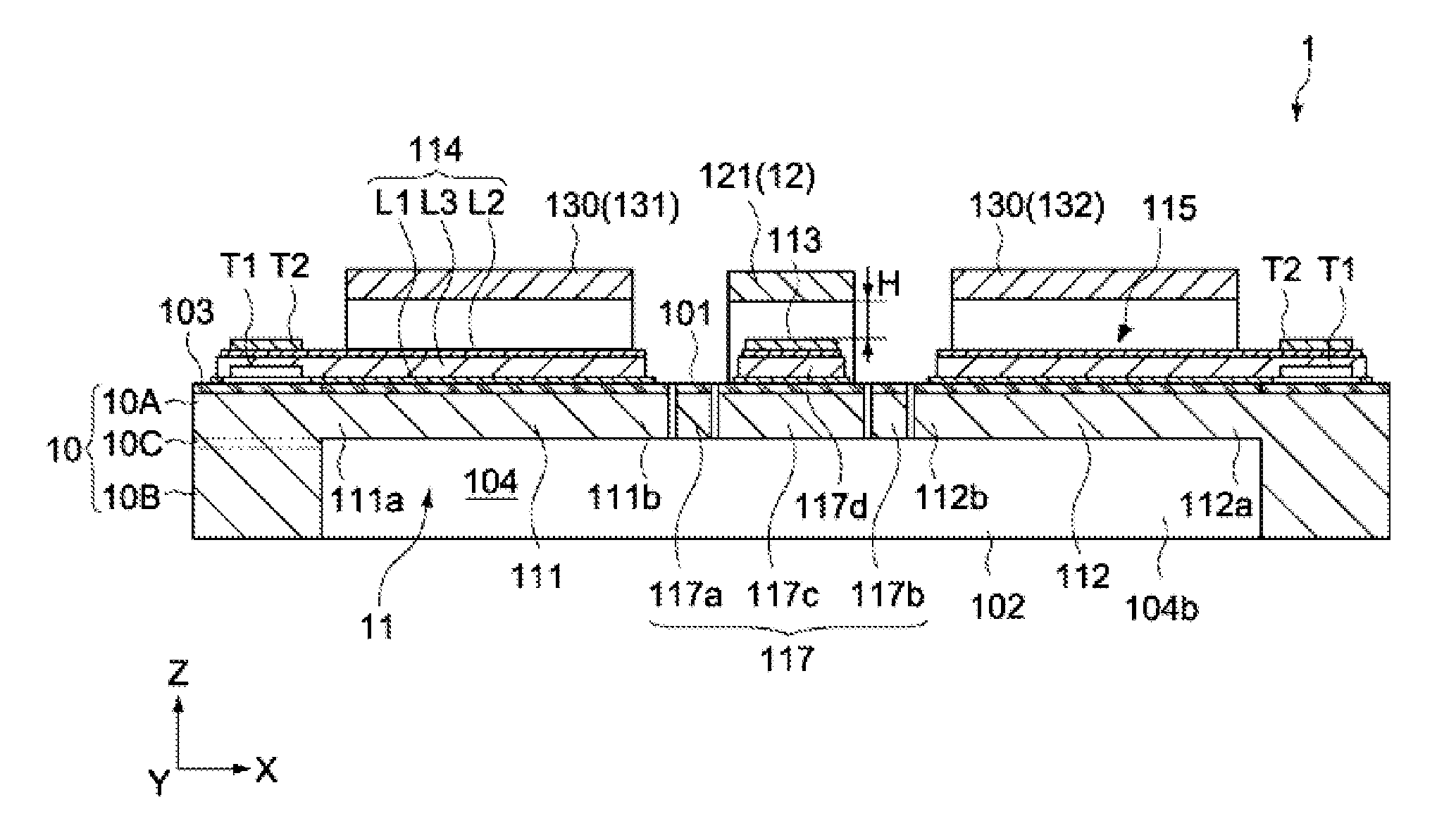
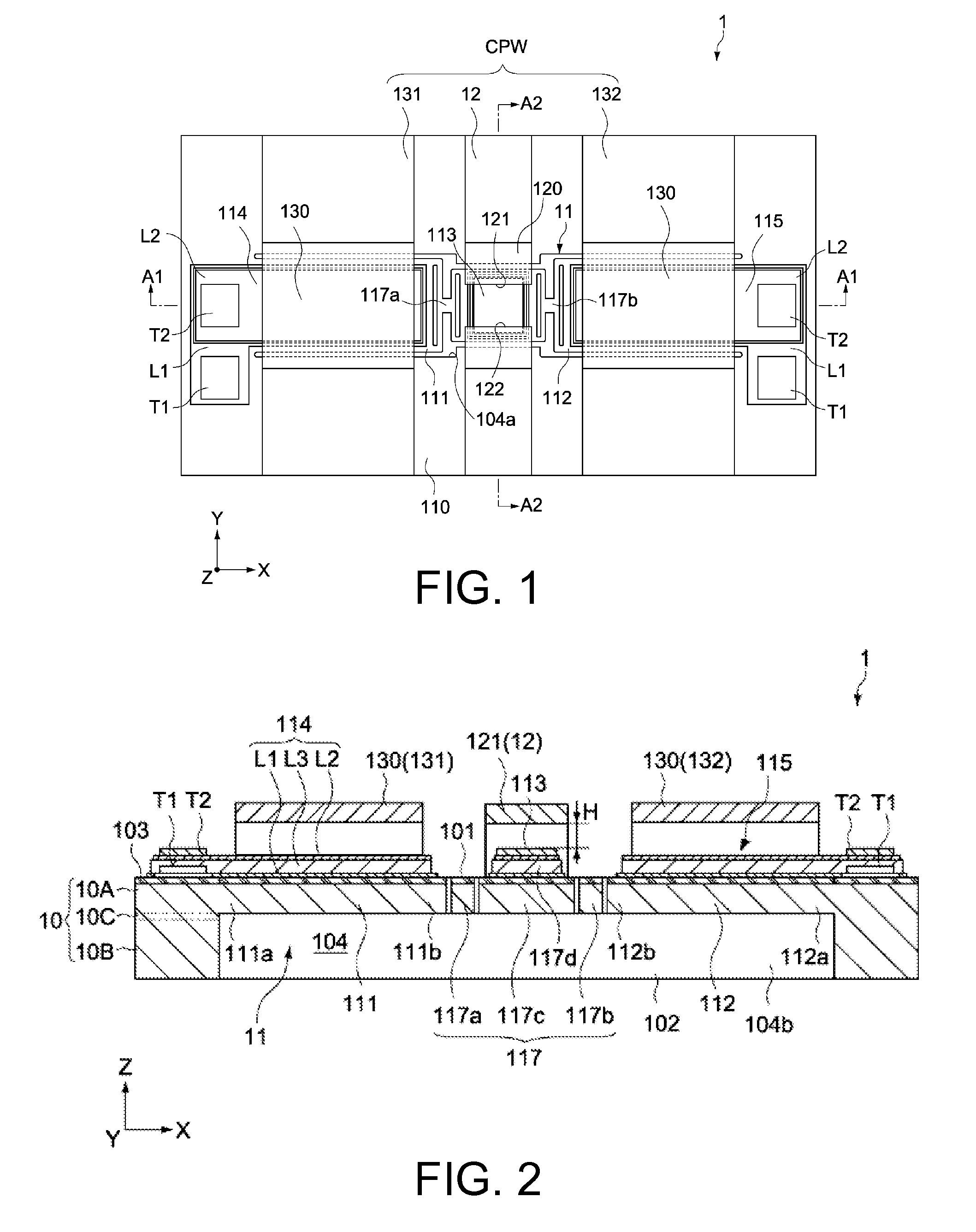
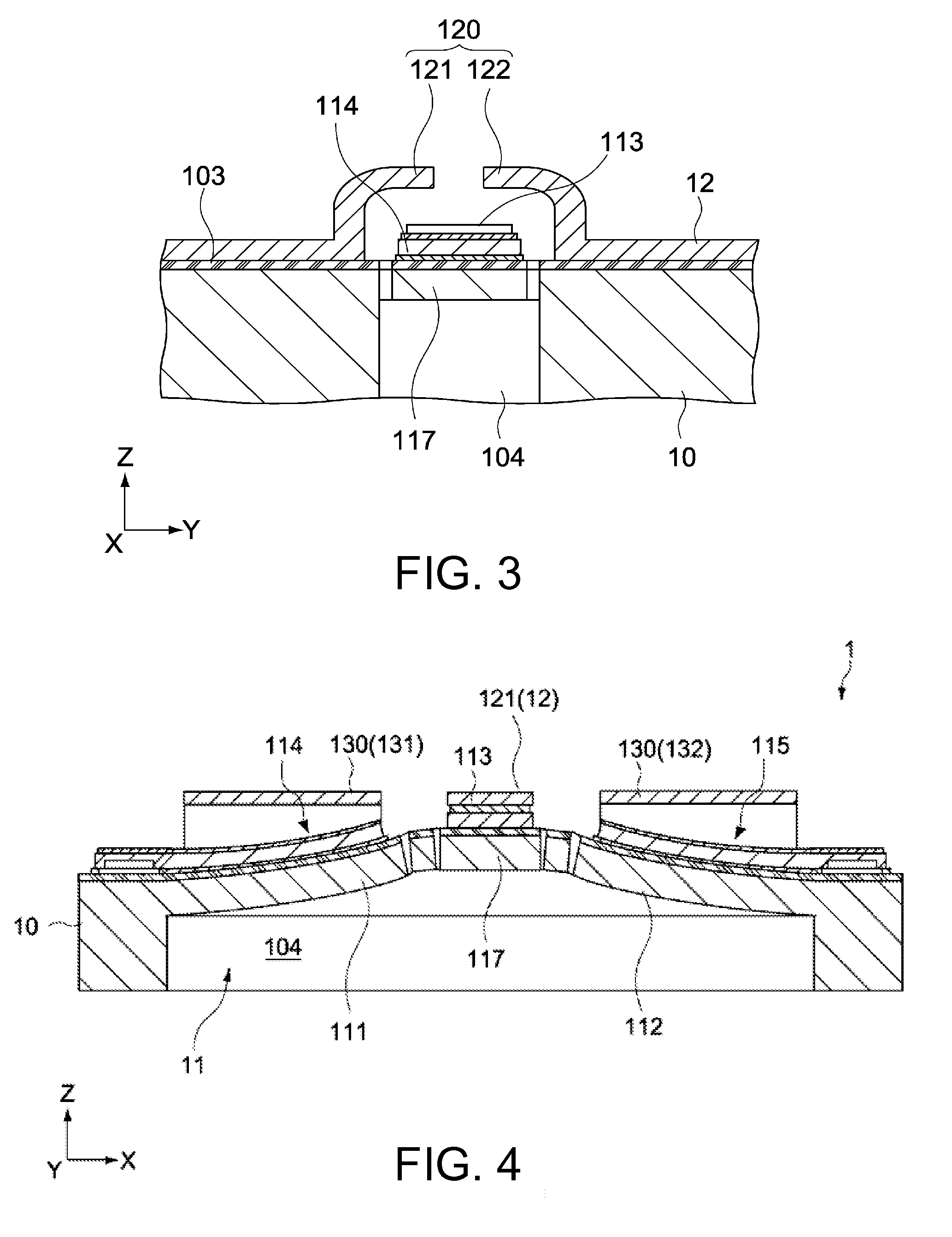
[0054]FIGS. 1 to 4 schematically show a configuration of a piezoelectric actuator according to Embodiment 1 of the present invention. FIG. 1 is a plan view of the piezoelectric actuator. FIG. 2 is a cross-sectional view along the line A1-A1 in FIG. 1. FIG. 3 is a cross-sectional view along the line A2-A2 in FIG. 1. FIG. 4 is a cross-sectional view showing an example of the mechanism of the piezoelectric actuator. In each figure, X axis and Y axis directions represent horizontal directions orthogonal to each other. Z axis represents a height direction orthogonal to the X axis and Y axis. In this embodiment, the piezoelectric actuator is constructed as a piezoelectric MEMS switch (piezoelectric switch).

[0055]The piezoelectric actuator 1 of this embodiment includes a base substrate 10, a moveable part 11, a signal line 12, and a pair of ground lines 131, 132.

[0056]The moveable part 11 has a first cantilever 111, a second cantilever 112, a ...

embodiment 2

[0131]FIG. 11 is a schematic cross-sectional view that shows a configuration of a piezoelectric actuating part of a piezoelectric actuator according to Embodiment 2 of the present invention. In this embodiment, descriptions of configurations and operations that are similar to those of Embodiment 1 are omitted or abridged, and differences from Embodiment 1 will be mainly described.

[0132]The piezoelectric actuating part of the piezoelectric actuator of this embodiment is constituted of a piezoelectric element D2 shown in FIG. 11. The piezoelectric element D2 differs from Embodiment 1 above in that the lower electrode layer L1 is made of the lower metal layer L11 only. Even with this configuration, the stress of the entire piezoelectric element D2 can be controlled by the upper electrode layer L2. As an example, when the upper conductive oxide layer L21 was made of LNO in a thickness of 0.15 μm, and the upper metal layer L22 was made of a Pt / Ti layer in a thickness of 0.33 μm, the uppe...


PUM

PropertyMeasurementUnit
temperatureaaaaaaaaaa
widthaaaaaaaaaa
lengthaaaaaaaaaa

Abstract

A piezoelectric actuator according to an embodiment of the present invention includes a base substrate provided with cantilevers and a piezoelectric element formed on each cantilever. The piezoelectric element includes: a lower electrode layer; a piezoelectric layer formed on the lower electrode layer; and an upper electrode layer having a conductive oxide layer formed on the piezoelectric layer. Because the conductive oxide layer has covalent bonds or ionic bonds, and therefore produces little plastic deformation, relaxation of the stress is less likely to occur. Thus, even with repetitive motion in the piezoelectric actuator, the as-deposited internal stress (film stress) can be stably maintained for a long period of time.

Description

[0001]This application claims the benefit of Japanese Application No. 2011-264202, filed in Japan on Dec. 2, 2011, which is hereby incorporated by reference in its entirety.BACKGROUND OF THE INVENTION[0002]1. Field of the Invention[0003]The present invention relates to a piezoelectric actuator that uses a piezoelectric element as an actuating part thereof, and to a method of manufacturing same.[0004]2. Description of Related Art[0005]An MEMS (Micro Electro Mechanical System) switch, a variable capacitor, a variable filter obtained by combining the two, and the like are known as actuators provided with a cantilever that is actuated by a piezoelectric element, for example. Patent Document 1 below, for example, describes a piezoelectric MEMS switch. In a piezoelectric MEMS switch, the higher the piezoelectric constant that is one of the material properties becomes, the lower the actuation voltage can be. Therefore, when using PZT, which is a typical piezoelectric material, for example,...

Claims


Application Information

Patent Timeline
Patent Type & Authority Applications(United States)
IPC IPC(8): H01L41/083H01H57/00H01L41/29H01L41/047
CPCH01L41/0838H01L41/0478H01H57/00Y10T29/42H01L41/0946H01H2057/006H01L41/29H10N30/878H10N30/2043H10N30/06H10N30/508
Inventor FUJII, TOMONORITAKANO, TAKAYUKI
Owner TAIYO YUDEN KK
Why Eureka
Try Eureka