Light emission apparatus, illumination system and illumination method

a technology of light emission apparatus and illumination system, which is applied in the direction of lighting and heating apparatus, process and machine control, instruments, etc., can solve the problems of difficult control, complex control of appropriate adjusting of driving current supplied to the respective led, and deterioration of color rendering properties that are important matters in typical illumination ligh

Inactive Publication Date: 2013-06-06
MITSUBISHI CHEM CORP
View PDF4 Cites 96 Cited by
  • Summary
  • Abstract
  • Description
  • Claims
  • Application Information

AI Technical Summary

Benefits of technology

[0018]The present invention has been made in view of such a problem, and provide a light emission apparatus capable of suppressing reduction in luminous flux inappropriate for adjustment of the color temperature while ensuring excellent color rendering properties, that is, a light emission apparatus capable of controlling the emission intensity and the color temperature so as to generate the light with a color temperature appropriate for the desired emission intensity and suppressing manufacturing costs, and an illumination system using the light emission apparatus. Further, the present invention provides an illumination method capable of emitting the light with the color temperature appropriate for the desired emission intensity by controlling the emission intensity and the color temperature while suppressing manufacturing costs of the light emission apparatus.
[0063]In the XY chromaticity diagram, the chromaticity of the first-order light emitted by each light emitting unit is determined such that the control curve is included in the polygon defined by vertices of the chromaticity points of the first-order light emitted by respective light emitting units. Hence, the light, which is generated from the light emission apparatus, is made to provide a sense of comfort all the time when the color temperature is changed.

Problems solved by technology

Hence, when the light emitted by the LED chips themselves is used in illumination as it is, a problem arises in that color rendering properties that are important matters in typical illumination light deteriorate.
However, in a similar manner to the light emission apparatus of JP-A-2007-122950, when a desired emission color is obtained by synthesizing the light respectively emitted by the blue LEDs, green LEDs, and red LEDs, for example, if the color temperature of the white light is intended to be changeable in a predetermined range, complex control for appropriately adjusting the driving currents supplied to the respective LEDs is necessary.
However, in such a light emission apparatus of JP-A-2007-122950, it is possible to generate white light with the desired color temperature through a complex control operation, but it is difficult to perform control so as to generate white light having the color temperature with respect to an optimum for the desired emission intensity mentioned above.
Hence, it is necessary to consider synthesis of the light emitted from a plurality of light-emitting sources in the entire range of the light control level, and thus a problem arises in that, in order to generate the white light with the desired color temperature, a process of calculating the driving currents supplied to the respective light-emitting sources becomes complicated every time.
Such a problem more frequently arises when the number of light-emitting sources increases.
Further, in the light emission apparatus disclosed in U.S. Pat. No. 7,288,902, the above-mentioned process of calculating the driving currents becomes complicated every time, and thus load on the driver control section and the driver increases.
In order to reduce the load on the driver control section and the driver, the driver control section and the driver with high processing capabilities are necessary, while a problem arises in that manufacturing costs of the light emission apparatus increase.
However, when the color temperature of the white light is changed, the luminance is unlikely to be appropriately changed in accordance with the change.
For example, the luminance may be excessively high when the color temperature is low, or the luminance may be excessively low when the color temperature is high.
For this reason, a problem arises in that the change of the color temperature may give a sense of discomfort to a person.
Accordingly, when the white light with the first color temperature is emitted from the illumination apparatus as described above, or when the white light with a color temperature close to the first color temperature is emitted, a problem arises in that the total luminous flux of the illumination light obtained from the illumination apparatus excessively deteriorates.

Method used


Image

  • Light emission apparatus, illumination system and illumination method
  • Light emission apparatus, illumination system and illumination method
  • Light emission apparatus, illumination system and illumination method

Examples


first example

Configuration of Light Emitting Section

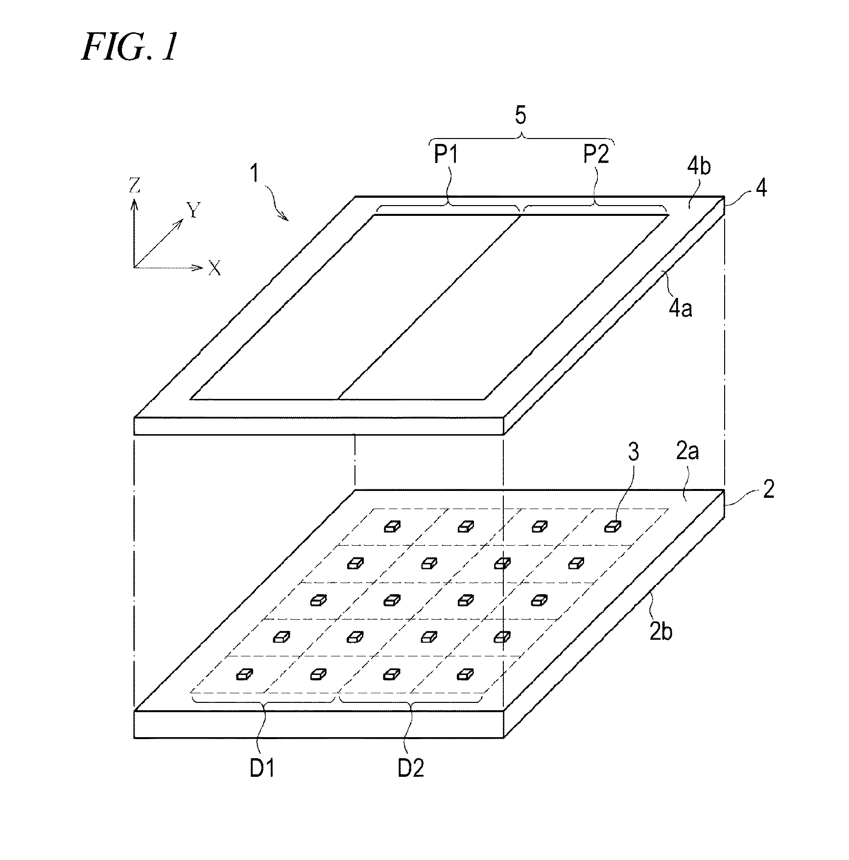
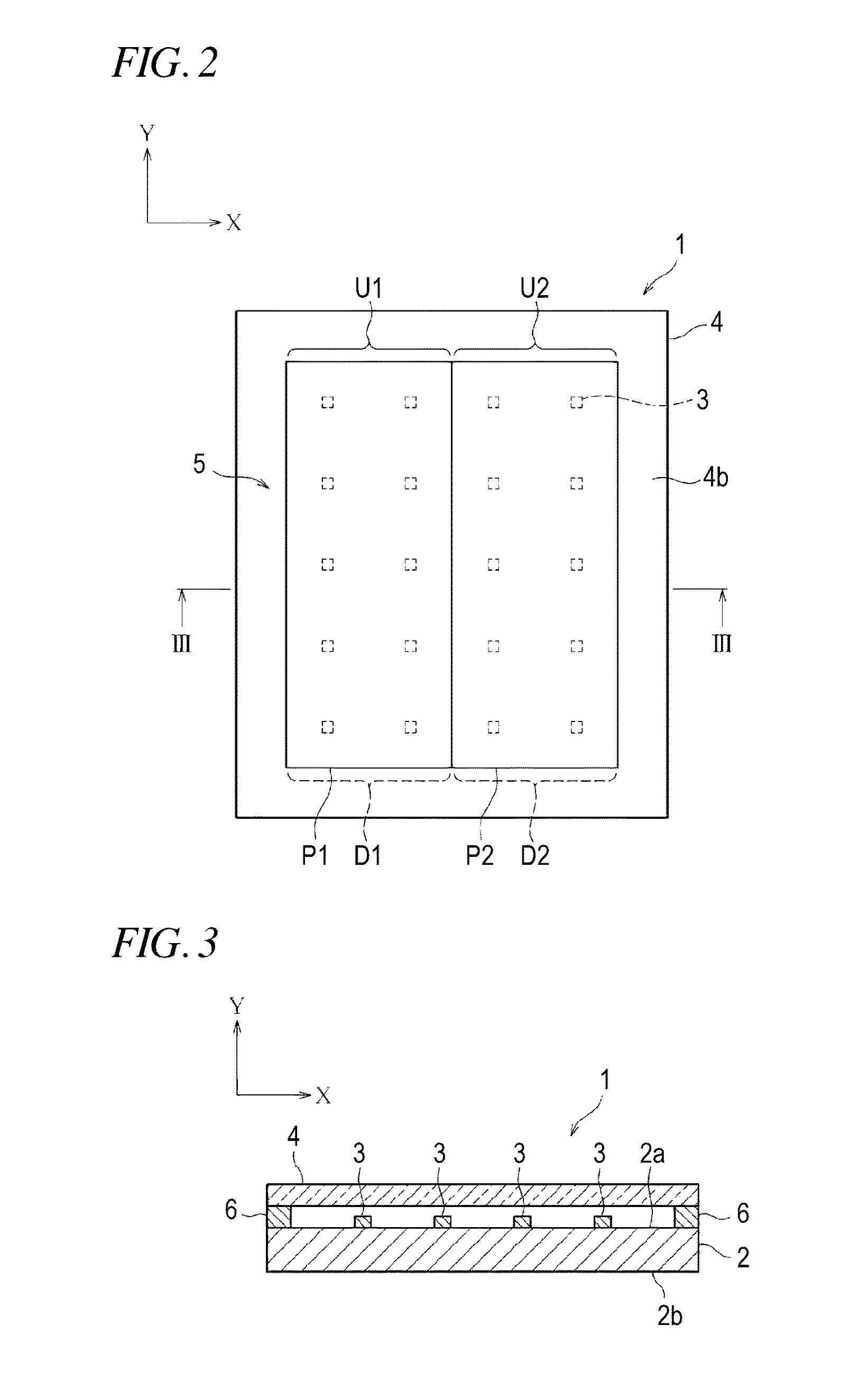
[0149]FIG. 1 is a perspective view illustrating an overview of an overall configuration of a light emitting section 1 in the light emission apparatus (illumination apparatus) according to the present example. FIG. 2 is a top plan view of the light emitting section 1 of FIG. 1. Note that, in FIGS. 1 and 2, the widthwise direction of the light emitting section 1 is defined as an X direction, the lengthwise direction thereof is defined as a Y direction, and the height direction thereof is defined as a Z direction. As shown in FIG. 1, the light emitting section 1 includes a wiring board 2 made of alumina ceramic which is excellent in electrical insulation and has a favorable heat dissipation ability. On a chip mounting surface 2a of the wiring board 2, a total of 20 light emitting diode (LED: Light Emitting Diode) chips 3 are equidistantly arranged in a matrix of four in the widthwise direction (that is, X direction) and five in the lengthwise dire...

second example

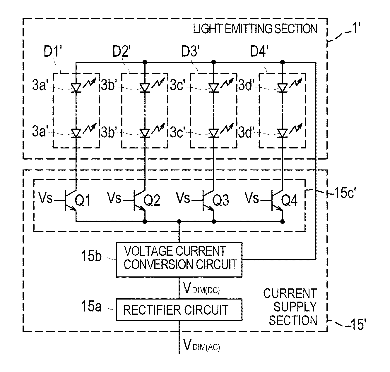
[0241]In the above-mentioned first example, the first wavelength conversion region P1 and the second wavelength conversion region P2, which emit first-order light with color temperatures different from each other, constitute the fluorescent member 5. That is, from the fluorescent member 5, the two types of the first-order light with different color temperatures are emitted. However, various modifications and variations may be made without departing from the technical scope of the invention. Therefore, examples of a light emitting section 1′, a light emission apparatus 11′ and an illumination system 12′, which are configured by using a fluorescent member 5′ having a different configuration from the configuration of the fluorescent member 5 of the first example, will be described below as a second example of the present invention. Note that, the members and components the same as the first example are represented by the same reference numerals and signs, and the description thereof wi...

third example

[0287]In the above-mentioned first example, the first wavelength conversion region P1 and the second wavelength conversion region P2, which emit first-order light with color temperatures different from each other, constitute the fluorescent member 5. That is, from the fluorescent member 5, the two types of the first-order light with different color temperatures are emitted. However, various modifications and variations may be made without departing from the technical scope of the invention. Therefore, examples of a light emitting section 1″, a light emission apparatus 11″ and an illumination system 12″, which are configured by using a fluorescent member 5″ having a different configuration from the configuration of the fluorescent member 5 of the first example, will be described below as a third example of the present invention. Note that, the members and components the same as the first example are represented by the same reference numerals and signs, and the description thereof wil...


PUM


Abstract

A light emission apparatus includes: a wiring board; a plurality of LED chips that are disposed on an LED chip mounting surface of the wiring board and are grouped into a plurality of LED groups; a wavelength conversion member that is disposed at a position corresponding to the LED chip mounting surface of the wiring board, converts a wavelength of light emitted by the corresponding LED chips, and emits first-order light with a different color temperature for each wavelength conversion region; a current supply section that supplies a driving current to the LED chips independently for each LED group through the wiring board; and a control section that controls the current amount supplied for each LED group in response to a control signal. The control section independently controls timing of starting to light the LED groups in accordance with the light control level.

Description

CROSS REFERENCE TO RELATED APPLICATIONS[0001]This application is a continuation of PCT application No. PCT / JP2011 / 070523, which was filed on Sep. 8, 2011 based on Japanese Patent Application (No. 2010-202493) filed on Sep. 9, 2010, Japanese Patent Application (No. 2011-051854) filed on Mar. 9, 2011, and Japanese Patent Application (No. 2011-186451) filed on Aug. 29, 2011, the contents of which are incorporated herein by reference. Also, all the references cited herein are incorporated as a whole.BACKGROUND[0002]1. Technical Field[0003]The present invention relates to a light emission apparatus using LED chips, which emit light with wavelengths in a predetermined wavelength range from the visible light region to the near-ultraviolet region, and a wavelength conversion member which converts the wavelength of the light emitted by the LED chips, and an illumination system using the apparatus. The present invention also relates to an illumination method for forming desired synthetic ligh...

Claims


Application Information

Patent Timeline
Patent Type & Authority Applications(United States)
IPC IPC(8): H05B33/08H05B44/00F21V9/40
CPCF21K9/56H01L2924/12041F21Y2105/003H01L25/0753H01L33/50H05B33/0857H05B33/0863F21V9/16H01L24/97H01L2224/16225H01L2924/01322H01L2924/13033H01L2924/1301H01L33/504F21Y2101/02H01L2924/00H01L2224/73265H01L2224/48091H01L2924/15747H01L2924/12044H01L2924/181F21Y2105/12F21Y2105/10F21K9/64F21Y2115/10H05B45/20F21V9/32F21V9/38F21V13/08H01L2924/00014H01L2924/00012
Inventor KODAMA, HIROYAKIJIMA, NAOTOTAKEDA, TORUHATTORI, EIJIKATSUMOTO, TADAHIROYOKOO, TOSHIAKIYOYASU, FUMIKOKOJIMA, TAKASHI
Owner MITSUBISHI CHEM CORP
Why Eureka
Try Eureka