
Device and method using induction to improve natural convection cooling

a technology of induction and cooling chamber, which is applied in the direction of lighting and heating apparatus, cooling/ventilation/heating modifications, electrical apparatus, etc., can solve the problems of large amount of heat that must be dissipated by switches, and achieve the effect of increasing the cooling capacity of the convective cooling chamber and increasing the air flow

Active Publication Date: 2013-06-06
ROCKWELL AUTOMATION TECH
View PDF8 Cites 26 Cited by
  • Summary
  • Abstract
  • Description
  • Claims
  • Application Information

AI Technical Summary

Benefits of technology

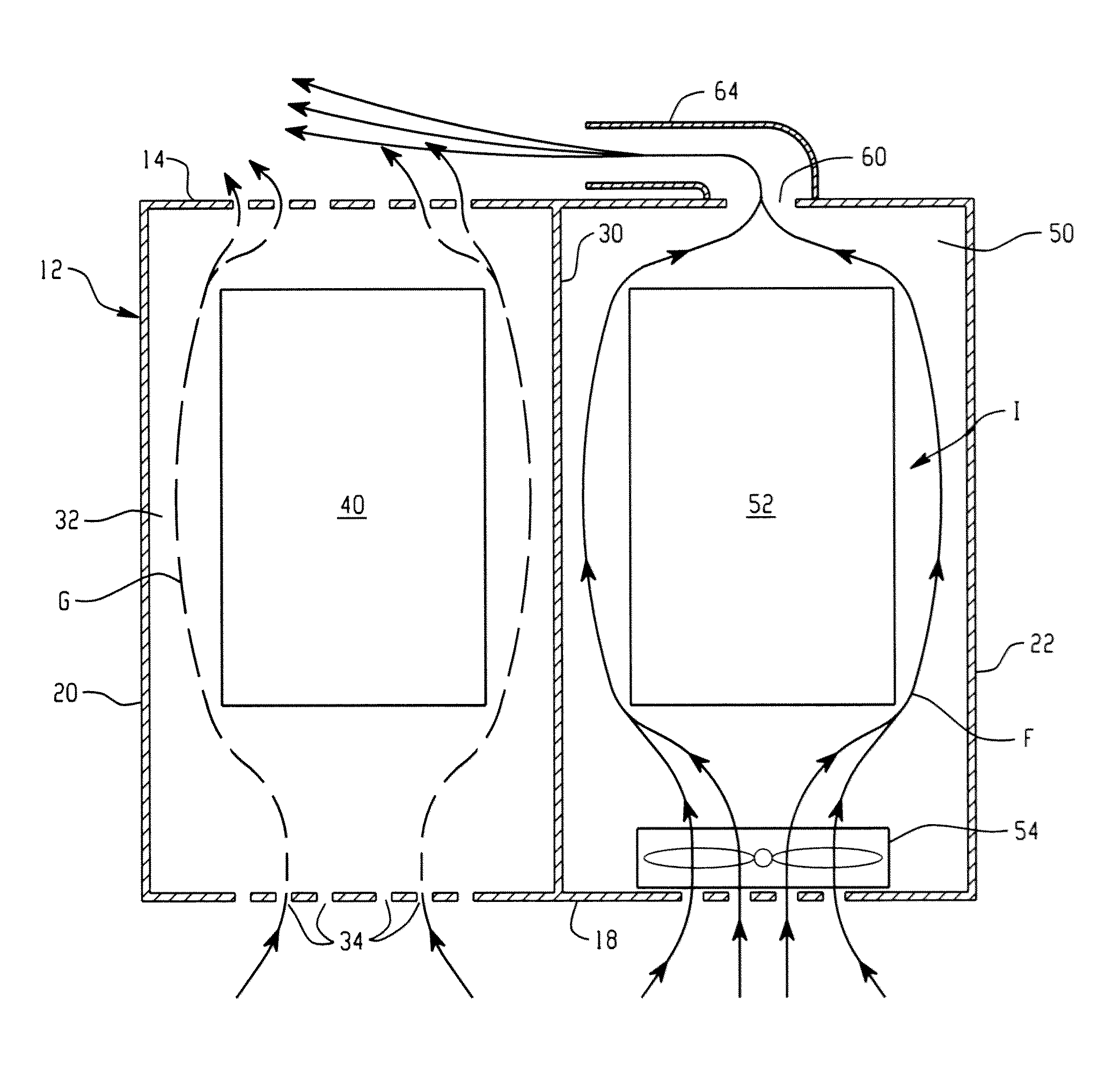
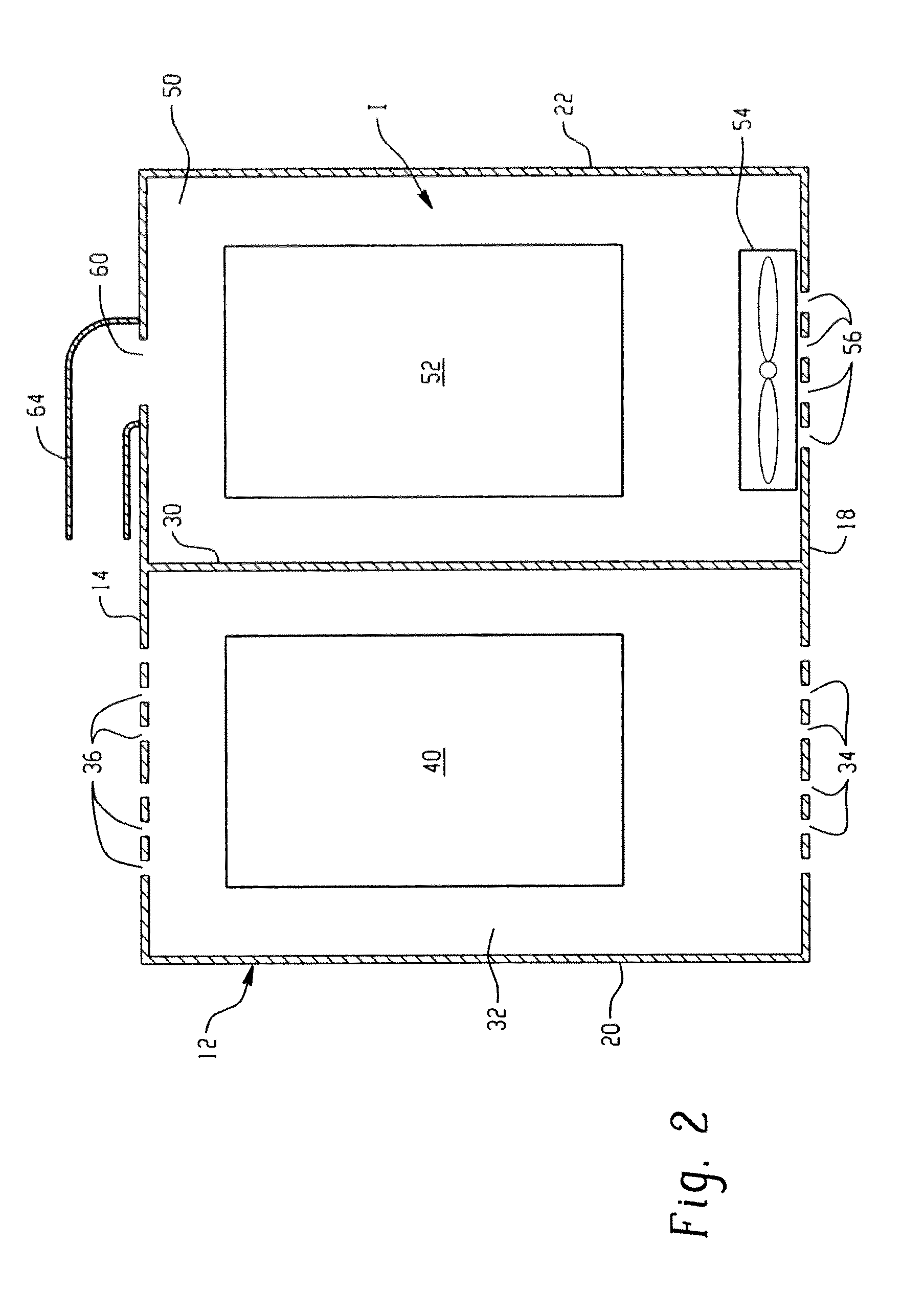
The present invention is for an air cooled switching unit for a motor drive. It includes two separate chambers: a forced air cooling chamber and a convective cooling chamber. The invention is about directing exhaust air from the forced cooling chamber onto the convective cooling chamber, which increases the air flow and cooling capacity of the convective chamber. This improves the unit's ability to handle higher temperatures and allows for better cooling efficiency.

Problems solved by technology

Regardless of the exact type, these switches generate large amounts of heat that must be dissipated.

Method used


Image

  • Device and method using induction to improve natural convection cooling
  • Device and method using induction to improve natural convection cooling
  • Device and method using induction to improve natural convection cooling

Examples


Embodiment Construction

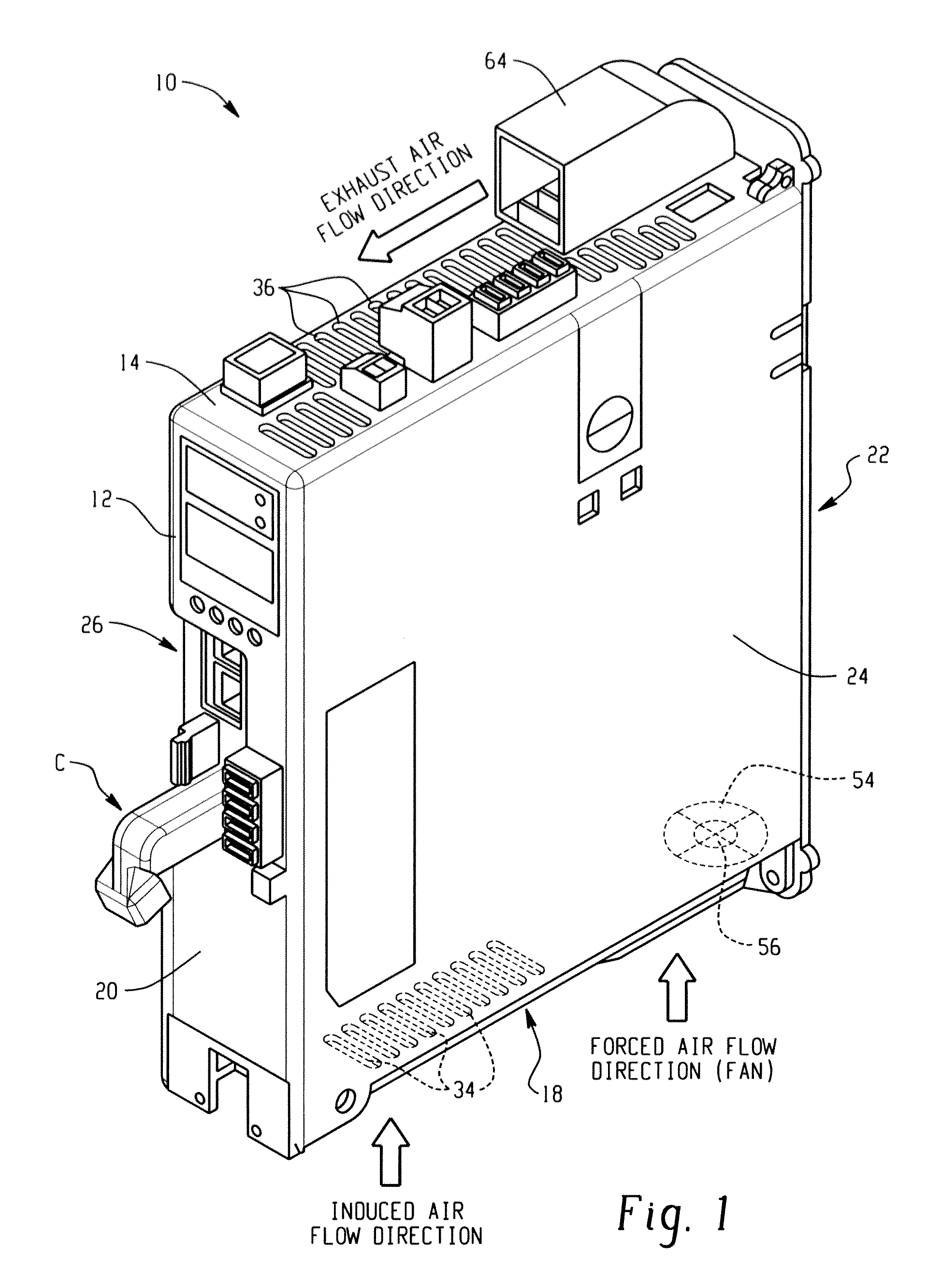
[0015]In FIG. 1, an exemplary motor drive 10 in accordance with the disclosure is illustrated for housing one or more switching units and / or other electrical components. As will be appreciated, the specific style and type of motor drive 10 is not necessarily significant and aspects of this disclosure are applicable to a wide range of electric cabinets designed to house heat-generating components, including various styles of motor drives, as well as other types of enclosures.

[0016]The motor drive 10 includes a housing 12 having a top panel 14, a bottom panel 18, a front panel 20, a rear panel 22, and side panels 24 and 26. One or more of the panels can be formed integrally, or each panel can be a separate component. The front panel 20 of the housing 12 includes one or more connectors C for connecting the drive 10 to a power source and / or a motor. The top and bottom panels 14 and 18 include openings for the flow of air into and out of the housing 12. Together, the panels of the housin...


PUM


Abstract

An air cooled switching unit for a motor drive includes a forced air cooling chamber and a convective cooling chamber separate from the forced air cooling chamber. An exhaust port of the forced cooling chamber is configured to direct exhaust air across an outlet of the convective cooling chamber to induce an increased air flow through the convective cooling chamber thereby increasing the cooling capacity of the convective cooling chamber.

Description

BACKGROUND[0001]Motor drives are power conversion systems or “converters” that operate to provide power to electric motors in a controlled fashion to control one or more motor performance parameters, such as speed, torque, etc. Low voltage current-sourced type motor drives typically receive multiphase AC input power in the range of about 240 to 690 volts, which is converted in a rectifier to DC power supplied to a DC link and provided from the DC link to an inverter. The inverter switches the DC link currents to provide AC output current to a motor load with the output current being controlled by the inverter in closed loop fashion to drive the motor at a desired speed and / or torque. The rectifier is generally an active switching type rectifier that selectively activates switches to provide current from the AC input to the DC link bus to achieve AC to DC power conversion, where the rectifier gain is controlled to provide a DC link current level at the peak current level required by ...

Claims


Application Information

Patent Timeline
IPC IPC(8): H05K7/20F28D15/00
CPCH05K7/20909H05K7/20127H05K7/20136
Inventor ZHOU, RUIBALCERAK, JOHN A.WINTERHALTER, CRAIG R.
Owner ROCKWELL AUTOMATION TECH
Learn More