Gait generating device for legged mobile robot and operational target generating device for robot

a technology of generating device and robot, which is applied in the direction of computer control, program control, instruments, etc., can solve the problems of operating target impairing the smooth operation of the robot, and achieve the effect of preventing the displacement amount of the join

Active Publication Date: 2013-06-06
HONDA MOTOR CO LTD
View PDF7 Cites 25 Cited by
  • Summary
  • Abstract
  • Description
  • Claims
  • Application Information

AI Technical Summary

Benefits of technology

[0031]With this configuration, the joint operation restrictive condition is converted to the condition that the linear matrix inequality holds. Therefore, determining a desired value of the particular-site motion velocity vector, by the desired particular-site motion velocity value determining unit, as a value of the particular-site motion velocity vector that can minimize the value of the aforesaid evaluation function within the range in which the restriction condition that the aforesaid linear matrix inequality holds is satisfied in the above-described manner makes it possible to ultimately determine a desired value of the particular-site motion velocity vector that can minimize the value of the aforesaid evaluation function within the range in which the aforesaid joint operation restriction condition is satisfied.
[0084]According to the sixth aspect of the invention, by the use of the above-described coefficient Kp, the instantaneous value of the future gait of the mobile robot within a period between the time corresponding to the latest desired gait and the time corresponding to the aforesaid new desired gait can be estimated, appropriately and in a simple manner, from the latest desired gait and the past desired gait immediately preceding the latest desired gait among the already determined desired gaits.

Problems solved by technology

As a result, an operational target impairing the smoothness in operation of the robot, or an operational target varying from the intended operational target ensuring a proper operation of the robot will be determined inevitably.

Method used


Image

  • Gait generating device for legged mobile robot and operational target generating device for robot
  • Gait generating device for legged mobile robot and operational target generating device for robot
  • Gait generating device for legged mobile robot and operational target generating device for robot

Examples


first embodiment

[0112]An embodiment of the present invention will be described below with reference to FIGS. 1 to 6.

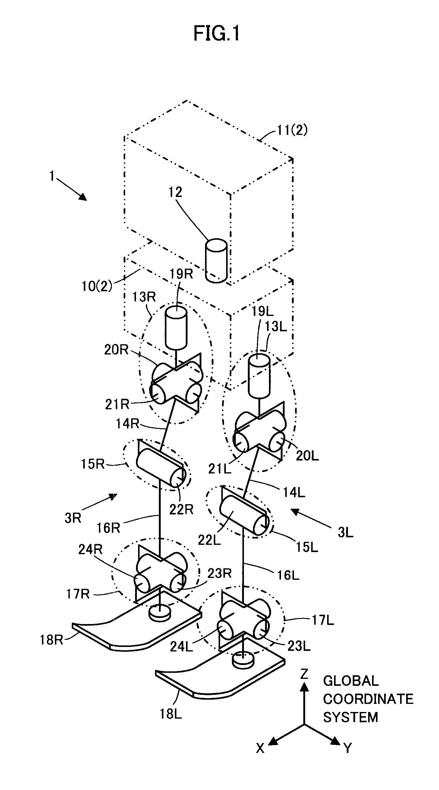
[0113]FIG. 1 is a schematic diagram illustrating the general construction of a legged mobile robot given as an example in the present embodiment. This legged mobile robot 1 (hereinafter, referred to simply as the robot 1) is a bipedal mobile robot which has a body 2 and a pair of right and left leg links 3R and 3L extended from the body 2.

[0114]In the present specification, a reference character “R” will be added to the reference characters indicating the members on the right side of the robot 1 facing forward or to the variables indicating the amounts related to those members, and a reference character “L” will be added to the reference characters indicating the members on the left side of the robot 1 facing forward or to the variables indicating the amounts related to those members. The reference characters “R” and “L”, however, may be omitted when it is not particularly necessary t...

second embodiment

[0351]A second embodiment of the present invention will now be described with reference to FIG. 12. The second embodiment is different from the above-described first embodiment only in part of the processing in the desired body motion velocity value determiner 45. Therefore, in the description of the present embodiment, the differences from the first embodiment will be described primarily; the description of the same features as in the first embodiment will not be repeated.

[0352]The present embodiment differs from the first embodiment only in the processing of determining ↑ωleg_i_min and ↑ωleg_i_max in the aforesaid linear matrix inequalities (10a) and (10b).

[0353]More specifically, in the present embodiment, the desired body motion velocity value determiner 45 determines the components of ↑ωleg_i_min and ↑ωleg_i_max for a leg link 3—i (3R or 3L), i.e. the upper and lower limits of the joint velocity of each joint of the leg link 3—i, in accordance with the displacement amount θ of ...


PUM


Abstract

A gait generating device 32 includes a desired particular-site motion velocity value determining unit 45 that uses a quadratic evaluation function having a particular-site motion velocity vector ↑Vb as a variable and a linear matrix inequality having ↑Vb as a variable to sequentially determine, as a desired value ↑Vb_cmd2 of ↑Vb, a value of ↑Vb that can minimize the value of the evaluation function within a range in which a restriction condition that the linear matrix inequality holds is satisfied, by arithmetic processing according to a solution method for a quadratic programming problem. The device then integrates ↑Vb_cmd2 to sequentially determine desired values of the position and posture of the particular site (the body) 2 of the robot 1. The linear matrix inequality is set to satisfy a condition restricting the operations of the joints between the particular site 2 and the distal portion of each leg link 3.

Description

BACKGROUND OF THE INVENTION[0001]1. Field of the Invention[0002]The present invention relates to a gait generating device for a legged mobile robot and an operational target generating device for a robot.[0003]2. Description of the Related Art[0004]Conventionally, as a technique of generating a desired gait of a legged mobile robot, a technique of setting targets for the translational momentum vector of the entire mobile robot (the translational momentum vector of the overall center of gravity) and the angular momentum vector of the entire mobile robot, and generating a desired gait that defines the displacement amount of each joint of the mobile robot so as to satisfy the targets has been proposed, as seen in, for example, “Resolved Momentum Control: Motion Generation of a Humanoid Robot based on the Linear and Angular Momenta”, Kajita, Kanehiro, Kaneko, Fujiwara, Harada, Yokoi, and Hirukawa, Journal of Robotics Society of Japan, Vol. 22, No. 6, pp. 772-779, 2004 (hereinafter, refe...

Claims


Application Information

Patent Timeline
Patent Type & Authority Applications(United States)
IPC IPC(8): B25J9/16
CPCB25J9/1607B62D57/032Y10S901/01
Inventor KANAZAWA, MASAOKANZAKI, SHIGERU
Owner HONDA MOTOR CO LTD
Why Eureka
Try Eureka