Microwave probe for furnace refractory material

a technology of refractory material and microwave probe, which is applied in the direction of instruments, lighting and heating apparatus, furnaces, etc., can solve the problems of distorted measurement wall thickness or flaw location, microwaves may penetrate the material and reflect from the opposite wall, etc., to suppress spurious reflection, improve signal isolation, and reduce loss

Active Publication Date: 2013-06-06
PANERATECH
View PDF3 Cites 31 Cited by
  • Summary
  • Abstract
  • Description
  • Claims
  • Application Information

AI Technical Summary

Benefits of technology

[0008]Disclosed is a system and method to aid in these inspections that avoid the disadvantages of the prior art. The system and method are operative to take thickness measurements of, and thus evaluate the condition of, materials including but not limited to refractory materials, operating in frequency bands that result in less loss than previously known technologies, and utilizing a system configuration and signal processing techniques that isolate the reflected signal of interest from other spurious antenna reflections, particularly by creating (through the configuration of the antenna assembly) a time delay between such spurious reflections and the actual reflected signal of interest, thus enabling better isolation of the signal of interest. Still further, the antenna assembly is intrinsically matched to the material to be probed, such as by impedance matching the antenna to the particular material (through knowledge of the dielectric and magnetic properties of the material to be evaluated) to even further suppress spurious reflections.

Problems solved by technology

Testing has shown that microwaves may penetrate the material and reflect from the opposite wall and / or from defects.
This means that measured wall thickness or flaw location is distorted.

Method used


Image

  • Microwave probe for furnace refractory material
  • Microwave probe for furnace refractory material
  • Microwave probe for furnace refractory material

Examples


Embodiment Construction

[0023]The following description is of a particular embodiment of the invention, set out to enable one to practice an implementation of the invention, and is not intended to limit the preferred embodiment, but to serve as a particular example thereof. Those skilled in the art should appreciate that they may readily use the conception and specific embodiments disclosed as a basis for modifying or designing other methods and systems for carrying out the same purposes of the present invention. Those skilled in the art should also realize that such equivalent assemblies do not depart from the spirit and scope of the invention in its broadest form.

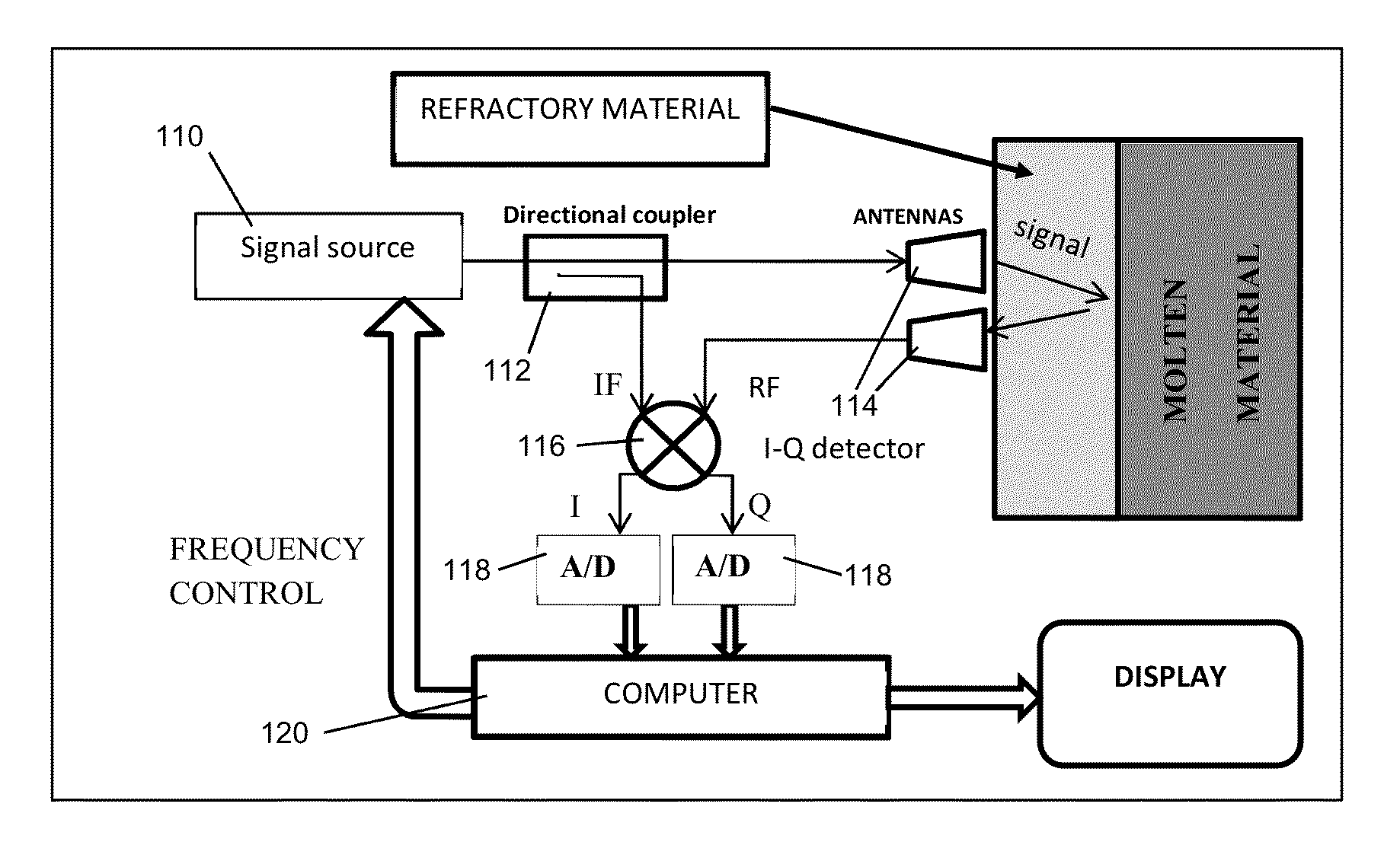
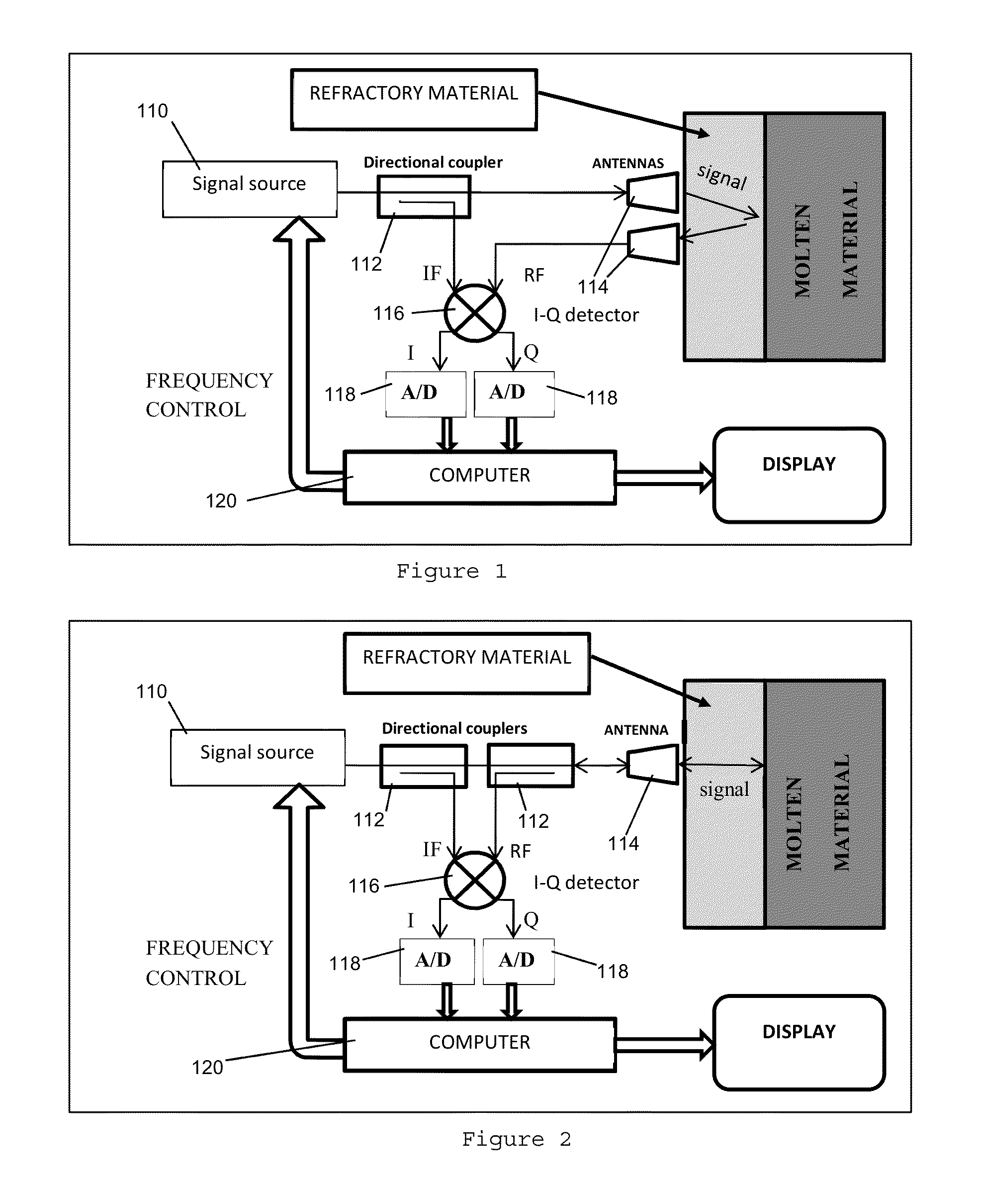
[0024]A basic system in an exemplary embodiment is a short range coherent radar configured to evaluate a remote surface (e.g., the interface between a furnace wall and molten material within the furnace) of a material that is to be evaluated. As used herein, “remote” surface is intended to refer to a surface of a material under evaluation that i...


PUM

PropertyMeasurementUnit
frequencyaaaaaaaaaa
frequencyaaaaaaaaaa
frequencyaaaaaaaaaa

Abstract

Disclosed is a system and method to aid in these inspections that avoid the disadvantages of the prior art. The system and method are operative to take thickness measurements of, and thus evaluate the condition of, materials including but not limited to refractory materials, operating in frequency bands that result in less loss than previously known technologies, and utilizing a system configuration and signal processing techniques that isolate the reflected signal of interest from other spurious antenna reflections, particularly by creating (through the configuration of the antenna assembly) a time delay between such spurious reflections and the actual reflected signal of interest, thus enabling better isolation of the signal of interest. Still further, the antenna assembly is intrinsically matched to the material to be probed, such as by impedance matching the antenna to the particular material (through knowledge of the dielectric and magnetic properties of the material to be evaluated) to even further suppress spurious reflections.

Description

CROSS REFERENCE TO RELATED APPLICATION[0001]This application is based upon and claims priority from co-pending U.S. Provisional Patent Application Ser. No. 61 / 567,331 entitled “Microwave Probe for Furnace Refractory Material,” filed with the U.S. Patent and Trademark Office on Dec. 6, 2011, by the inventors herein, the specification of which is incorporated herein by reference.GOVERNMENT LICENSE RIGHTS[0002]This invention was made with Government support under SBIR Phase I Grant No. IIP-1113770 awarded by the National Science Foundation. The Government has certain rights in the invention.FIELD OF THE INVENTION[0003]This invention relates generally to systems and methods for inspecting the condition of surfaces through measured reflection of transmitted energy, and more particularly to systems and methods for evaluating the condition of refractory materials using microwave radiation.BACKGROUND OF THE INVENTION[0004]Various industries in the world use large furnaces to melt and hold t...

Claims


Application Information

Patent Timeline
Patent Type & Authority Applications(United States)
IPC IPC(8): G01B15/02G06F15/00
CPCG06F15/00G01B15/02F27D21/0021G01N22/02
Inventor WALTON, ERICBAYRAM, YAKUP
Owner PANERATECH
Why Eureka
Try Eureka