Method for forming a package, a package and a package blank

Inactive Publication Date: 2013-06-13
NEC CORP +1
11 Cites 2 Cited by

AI-Extracted Technical Summary

Problems solved by technology

Apart from being a visual defect, the curved shape of the rim may give technical problems during sealing of the lid to the tray package.
However some plasti...

Method used

[0025]The moulding operation where the package is formed from the blank is preferably a compression molding using a press tool which deforms the blank and urges it to the final shape. The package obtains its final shape when the cardboard blank is pressed between two mould halves. During this operation the margin area 2 will be bent upwards from the middle portion 1 which retains its original orientation and forms the bottom of the package. The margin area 2 will form the side walls of the package around the bottom, limiting the inner volume of the package laterally in all directions. Due to the moulding operation the transition zone 3 between the middle portion 1 and the margin area 2 will undergo bending deformation in a direction perpendicular to the plane of the blank. This zone 3, where the side walls connect to the bottom, will have a curved shape seen in vertical cross-section of the package. To reduce or eliminate internal stresses caused by this deformation, the transition zone 3 contains elongated areas 4 of reduced bending stiffness. In the blank shown in FIG. 1 there are four such areas 4 around the middle portion 1, two in parallel with the shorter sides of the blank and two in parallel with the longer sides of the blank. The areas 4 ar...

Benefits of technology

[0018]The present invention further relates to a package blank of planar shap...

Abstract

The present invention relates to a method for forming a package by moulding a cardboard blank in such a manner that a margin area (2) of the blank, surrounding a middle portion (1) of the blank, is bent upwards to form side walls of the package while the middle portion forms a bottom of the package. The cardboard blank prior to moulding is provided with at least one area (4) of reduced bending stiffness being located in a transition zone (3) between the side walls and the bottom. The package is moulded from the blank so that the at least one area (4) of reduced bending stiffness is located in the bended areas between the side walls and the bottom and extend in the running direction of the bend. The invention further relates to a package and a package blank that can be used for forming said package.

Application Domain

Envelopes/bags making machineryBox making operations +6

Technology Topic

Flexural rigidityEdge region +2

Image

  • Method for forming a package, a package and a package blank
  • Method for forming a package, a package and a package blank

Examples

  • Experimental program(1)

Example

[0022]The term “package” shall in this context mean either a closed package or an open package capable of taking a product to be packed and the package should be closable by a lid or similar closure.
[0023]The blank shown in FIG. 1 is a cardboard blank where the cardboard may be coated on one side, both sides or it may be uncoated. If the package made of the blank is for packaging food products, the coating on the blank may be a barrier material giving the blank barrier properties, for example a barrier against liquid, vapor, grease etc. The coating may consist of one layer or it can have two or several layers. Coatings used in cardboard packaging materials are widely known and they are not discussed in further detail in this context.
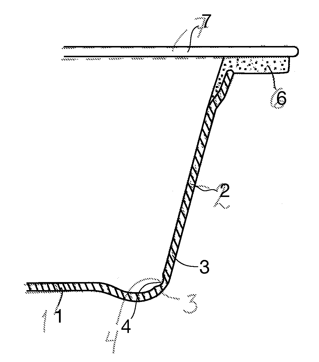
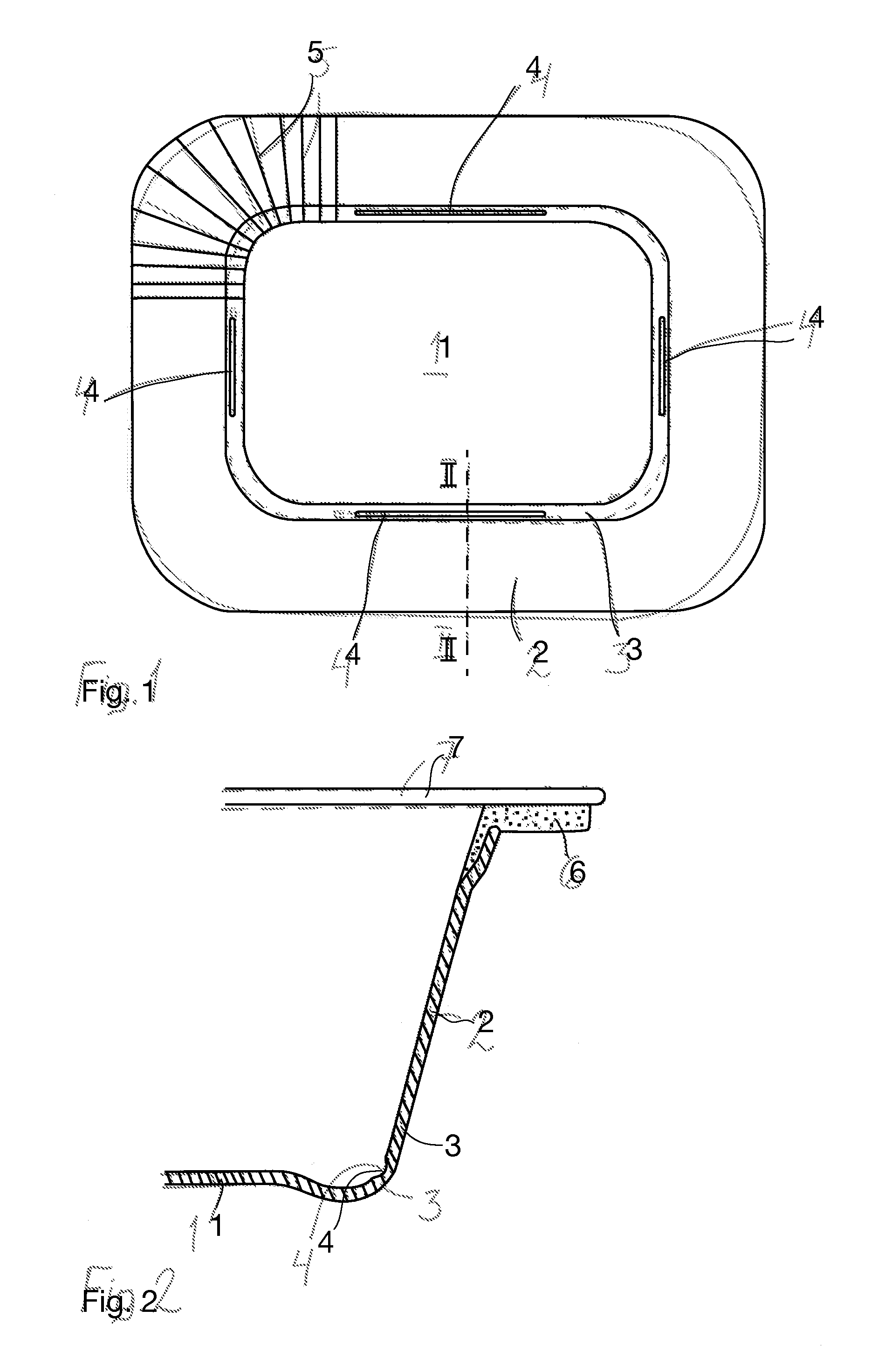
[0024]The blank is of general rectangular shape with successive straight sides and rounded corners at its outer edge, which is a widely used shape for tray-type containers. The blank has a middle portion 1 which is surrounded by a margin area 2 which is outwardly limited by the outer edge of the blank. The corners of the margin area 2 comprise radially extending score lines 5, or the like known as such, which will help to form the corners of the package during the molding operation.
[0025]The moulding operation where the package is formed from the blank is preferably a compression molding using a press tool which deforms the blank and urges it to the final shape. The package obtains its final shape when the cardboard blank is pressed between two mould halves. During this operation the margin area 2 will be bent upwards from the middle portion 1 which retains its original orientation and forms the bottom of the package. The margin area 2 will form the side walls of the package around the bottom, limiting the inner volume of the package laterally in all directions. Due to the moulding operation the transition zone 3 between the middle portion 1 and the margin area 2 will undergo bending deformation in a direction perpendicular to the plane of the blank. This zone 3, where the side walls connect to the bottom, will have a curved shape seen in vertical cross-section of the package. To reduce or eliminate internal stresses caused by this deformation, the transition zone 3 contains elongated areas 4 of reduced bending stiffness. In the blank shown in FIG. 1 there are four such areas 4 around the middle portion 1, two in parallel with the shorter sides of the blank and two in parallel with the longer sides of the blank. The areas 4 are of limited length and separate from each other in the circumferential direction. They extend in parallel with the straight sections of the short sides and long sides of the blank, but they do not continue till the curved corner sections, i.e. they are discontinuous. By separating the areas of reduced bending stiffness it is possible to optimize the size, such as length, thickness and width, of the areas in a more effective way since the size of each area can be made different. In this way a more flexible and efficient way of reducing or even eliminating the deformation of the package can be achieved.
[0026]FIG. 2 illustrates the location of the area 4 of reduced bending stiffness in the moulded package, which is a so called tray-type container. The figure shows the side wall, the bend between the side wall and the bottom, and part of the bottom. The area 4 of reduced bending stiffness extends along the running direction of the bend. The running direction of the bend is the direction where the cross-section of the bend remains constant and it corresponds to the direction of the transition zone 3 in the blank. The area 4 is in the bend preferably in an angular position of about 40-50°, preferable about 45°, down from the horizontal, that is, where the radius connecting the centre of curvature of the bend and the area 4 forms an angle of about 40-50° with the horizontal plane on the side of the side wall. However, the said area 4 has stress relieving effect in cardboard material in all spots where deformation due to bending of the margin area away from the original plane of the blank has occurred.
[0027]The areas 4 of reduced bending stiffness, which can be designated “weaker areas”, are most conveniently formed by making the blank thinner, which automatically reduces the bending stiffness compared with the blank which has original thickness. The area 4 is of predetermined width, preferably over 1 mm and more preferably over 2 mm. Suitable width of the area is between 1-5 mm, preferably between 2.5-4.0 mm, but the area may be even wider. The width of the area 4 can be fixed for example by choice of the number of creasing blades that make the blank thinner. By using multiple parallel creasing blades any desired width of the area 4 can be obtained.
[0028]FIG. 2 shows also a horizontal edge flange or rim 6 extending outwardly from the upper edge of the side walls and surrounding the package. The flange 6 is formed separately from plastic material, for example thermoplastic polymer. Even though the flange 6 is not the same material as the cardboard blank, it can be fixed to the tray-type container during the same moulding operation where the container is formed. The flange can be made by injecting the material to a moulding cavity that is opened in a suitable moment in the press tool, as explained in the international publication WO 2009/074721. A lid 7 that is sealed to the upper surface of the flange 6 to close the package is designated by broken lines. The lid 7 is preferably made of cardboard whose lower surface has been coated with a material that is compatible with the material of the flange 6, for example for sealing the lid tightly and/or for allowing reclosability. The lid 7 may also be a plastic film comprising one or more layers and sealed to the upper surface of the flange 6. Such a film may be transparent so that the content of the package can be viewed without opening the package. It is also possible that the lid 7, irrespective of its material, is attached to the flange 6 mechanically only.
[0029]Even if the above-described package is particularly well suited for packaging of food in a tight manner which prevents diffusion of substances into and/or out of the closed package, it is also suitable for products other than food.
[0030]The shape of the blank and the resulting package need not necessary be rectangular. The shape can also be square where all sides have equal lengths. The shapes of other polygons are also possible. It is also possible that the blank and the package formed thereof has an oval shape.
[0031]The at least one area of reduced bending stiffness can also go uninterruptedly around the entire blank, surrounding its middle portion. Since the compression or forming of the area of reduced bending stiffness is preferably done at the same time as the forming of the score lines in the corner, it might not be possible to provide the corners with the areas of reduced bending stiffness in one process step. However, if the creases are formed in two steps it is possible to provide also the corners, i.e. the area with radially extended score lines, with areas of reduced bending stiffness.
[0032]The area/areas of reduced bending stiffness can be located either on the inside or on the outside of the package, because they will have similar effect on both locations. Thus, creasing can be performed on either side of the blank. In relation to FIG. 1, this means that the areas could be on the top side or on the bottom side of the blank. Furthermore, the invention can be applied both in packages made entirely of cardboard material and packages having a plastic rim described above. The invention is especially advantageous in cases where the shrinking of the plastic material of the rim in relation to the cardboard material causes the above-mentioned slight deformation problems in the moulded package.
[0033]It is contemplated that there are numerous modifications of the embodiments described herein, which are still within the scope of the invention as defined by the appended claims.

PUM

PropertyMeasurementUnit
Width0.001m
Width0.002m
Width0.0025 ~ 0.004m

Description & Claims & Application Information

We can also present the details of the Description, Claims and Application information to help users get a comprehensive understanding of the technical details of the patent, such as background art, summary of invention, brief description of drawings, description of embodiments, and other original content. On the other hand, users can also determine the specific scope of protection of the technology through the list of claims; as well as understand the changes in the life cycle of the technology with the presentation of the patent timeline. Login to view more.

Similar technology patents

Classification and recommendation of technical efficacy words

  • reduce bending stiffness
Why Eureka
Try Eureka