High-sensitivity transparent gas sensor and method for manufacturing the same

a gas sensor, high-sensitivity technology, applied in nanosensors, material analysis, instruments, etc., can solve the problems of opaque and expensive semiconductor gas sensors, no transparent gas sensors with excellent light transmittance in the visible region without sacrificing performance, etc., to achieve excellent response, superior gas sensitivity, and low cost

Inactive Publication Date: 2013-06-13
KOREA INST OF SCI & TECH
View PDF10 Cites 12 Cited by
  • Summary
  • Abstract
  • Description
  • Claims
  • Application Information

AI Technical Summary

Benefits of technology

[0020]Since the transparent gas sensor according to the present disclosure is transparent, it can be mounted on transparent electronic devices or transparent products such as windowpanes. Further, it exhibits superior gas sensitivity even without heat supply from outside owing to the excellent response provided by the nanocolumnar structure. In addition, it can be provided at low cost and can be mounted on mobile devices such as mobile phones because of low power consumption.

Problems solved by technology

However, no transparent gas sensor with excellent light transmittance in the visible region without sacrificing performance has been reported as yet.
In addition, despite the many advantages over the electrochemical or optical gas sensors, the existing semiconductor gas sensors are not widely used for practical applications for the following reasons.
First, the semiconductor gas sensor is opaque and expensive.
And, the noble metal such as platinum (Pt) or gold (Au) used in the electrode is expensive.
In addition, since the process of forming the electrode (metal layer) and the process of depositing the gas-sensing layer (metal oxide film) is not compatible with each other, large-scale production is difficult.
Besides, the existing semiconductor gas sensor lacks reliability due to inaccurate change in resistance of the gas-sensitive material because of high contact resistance between the metal (e.g., Pt) of the electrode and the gas-sensing layer (metal oxide film).
In addition, it consumes a lot of power.

Method used


Image

  • High-sensitivity transparent gas sensor and method for manufacturing the same
  • High-sensitivity transparent gas sensor and method for manufacturing the same
  • High-sensitivity transparent gas sensor and method for manufacturing the same

Examples


example 1

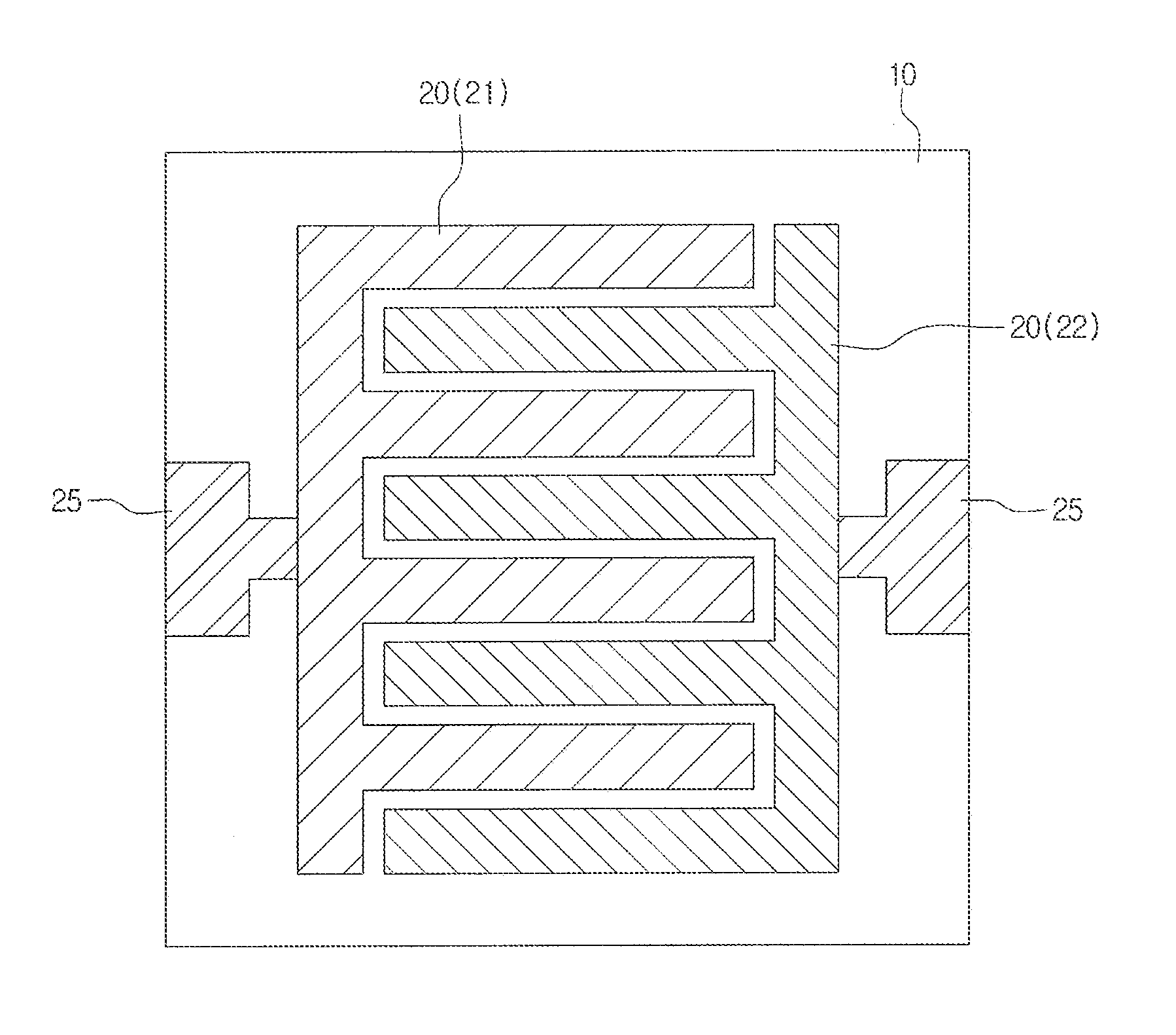
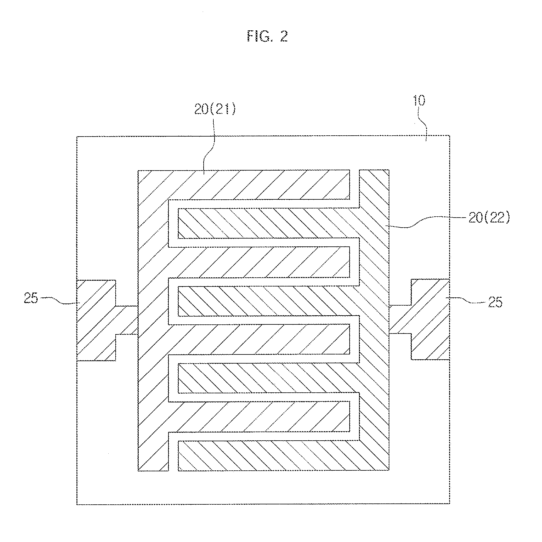
[0066]First, a glass substrate was mounted on a sputtering apparatus. Then, indium tin oxide (ITO) film was deposited on the glass substrate by axis RF sputtering. The ITO film was deposited for about 30 minutes using a sputter gun with an ITO target comprising 90 wt % In2O3 and 10 wt % SnO2 loaded, with 150 W RF power using pure argon (Ar) gas at 10 mTorr. Subsequently, the ITO film was dry etched to form a patterned transparent electrode in the form of an interdigitated electrode (hereinafter, referred to as ‘IDE transparent electrode’).

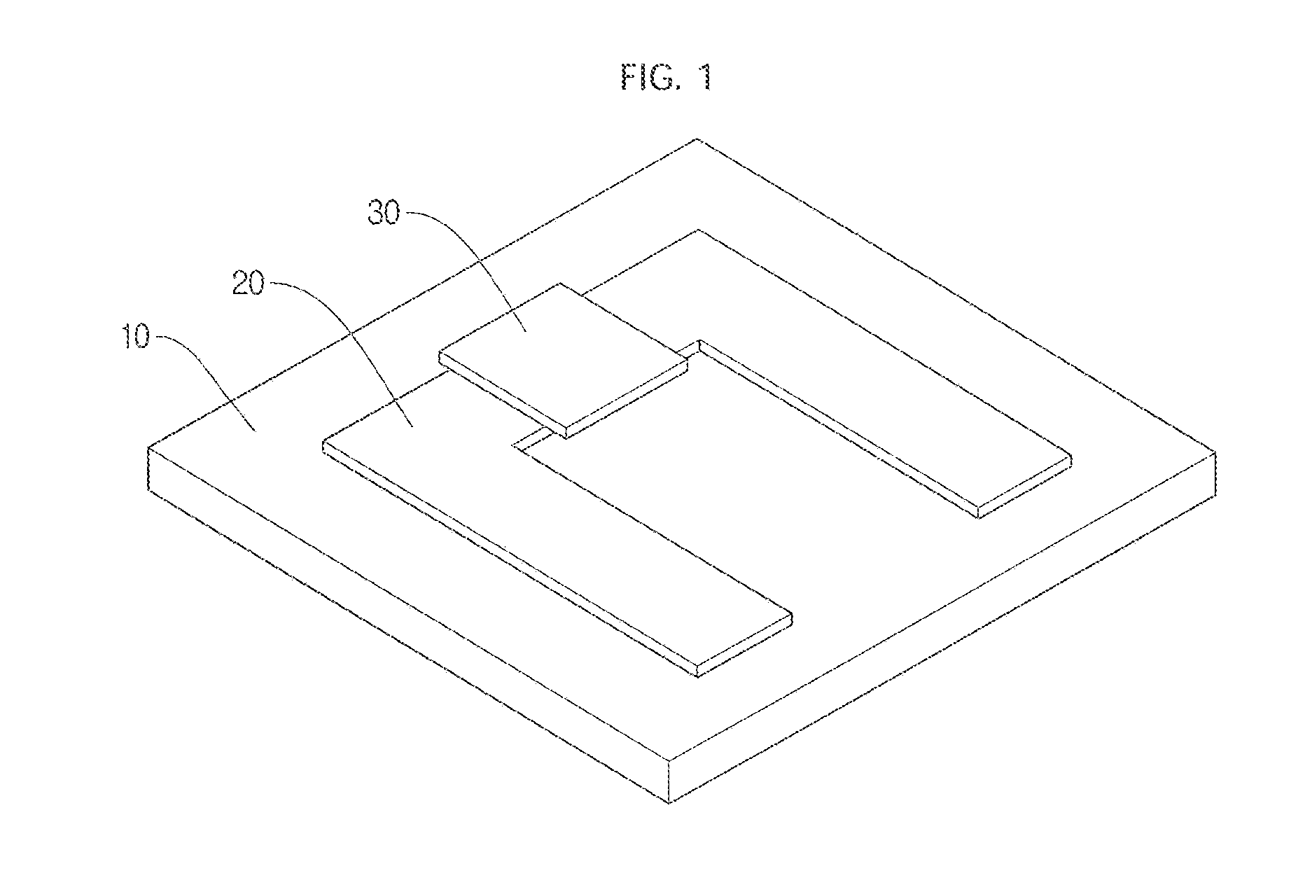
[0067]Then, tungsten oxide (WO3) layer was deposited on the patterned IDE transparent electrode as a gas-sensing layer by axis RF sputtering as described above. When depositing the WO3 layer, the sputtering was performed with the angle between a sputter gun with a WO3 target loaded and a substrate holder maintained at about 85°. As a result, a transparent gas sensor having WO3 / ITO / glass layer wherein the WO3 layer has a nanocolumnar structure was m...

examples 2-5

[0083]Gas sensors were manufactured as in Example 1 by varying the materials of a gas-sensing layer. Specifically, when forming the gas-sensing layer having a nanocolumnar structure on an IDE transparent electrode by sputtering, different targets were used to form SnO2 layer (Example 2), Nb2O5 layer (Example 3), ZnO layer (Example 4) and In2O3 layer (Example 5) as the gas-sensing layer having the nanocolumnar structure on the IDE transparent electrode.


PUM

PropertyMeasurementUnit
angleaaaaaaaaaa
band gapaaaaaaaaaa
power consumptionaaaaaaaaaa

Abstract

Disclosed are a high-sensitivity transparent gas sensor and a method for manufacturing the same. The transparent gas sensor includes a transparent substrate, a transparent electrode formed on the transparent substrate and a transparent gas-sensing layer formed on the transparent electrode. The transparent gas-sensing layer has a nanocolumnar structure having nanocolumns formed on the transparent electrode and gas diffusion pores formed between the nanocolumns.

Description

CROSS-REFERENCE TO RELATED APPLICATIONS[0001]This application claims priority under 35 U.S.C. §119 to Korean Patent Application No. 10-2011-0132714, filed on Dec. 12, 2011, in the Korean Intellectual Property Office, the disclosure of which is incorporated herein by reference in its entirety.BACKGROUND[0002]1. Field[0003]The present disclosure relates to a high-sensitivity transparent gas sensor and a method for manufacturing the same. More particularly, the present disclosure relates to a high-sensitivity transparent gas sensor having high light transmittance as well as superior gas sensitivity even when no heat is applied from outside and consuming less power, and a method for manufacturing the same.[0004]2. Description of the Related Art[0005]Gas sensors for detecting toxic gas, explosive gas, environmentally harmful gas, etc. are important in many fields including health care, national defense, counter-terrorism and environment. Researches are consistently ongoing on the gas sen...

Claims


Application Information

Patent Timeline
Patent Type & Authority Applications(United States)
IPC IPC(8): H01L29/12H01L21/02B82Y15/00
CPCB82Y15/00G01N27/12B82Y40/00G01N27/407
Inventor JANG, HO WONYOON, SEOK JINKIM, JIN SANGKANG, CHONG YUNCHOI, JI WONMOON, HI GYU
Owner KOREA INST OF SCI & TECH
Why Eureka
Try Eureka