Brake System for Motor Vehicles

a technology for brake systems and motor vehicles, applied in braking systems, braking components, transportation and packaging, etc., can solve the problems of too costly signal emitter, servo use, and save development and production costs,

Active Publication Date: 2013-06-13
CONTINENTAL TEVES AG & CO OHG
View PDF12 Cites 46 Cited by
  • Summary
  • Abstract
  • Description
  • Claims
  • Application Information

AI Technical Summary

Problems solved by technology

This saves development and production costs.
This means that the servo is used only when the regular pressure build-up by means of the pressure-generating device is not possible because of malfunctions and/or contr...

Method used


Image

  • Brake System for Motor Vehicles
  • Brake System for Motor Vehicles

Examples


Embodiment Construction

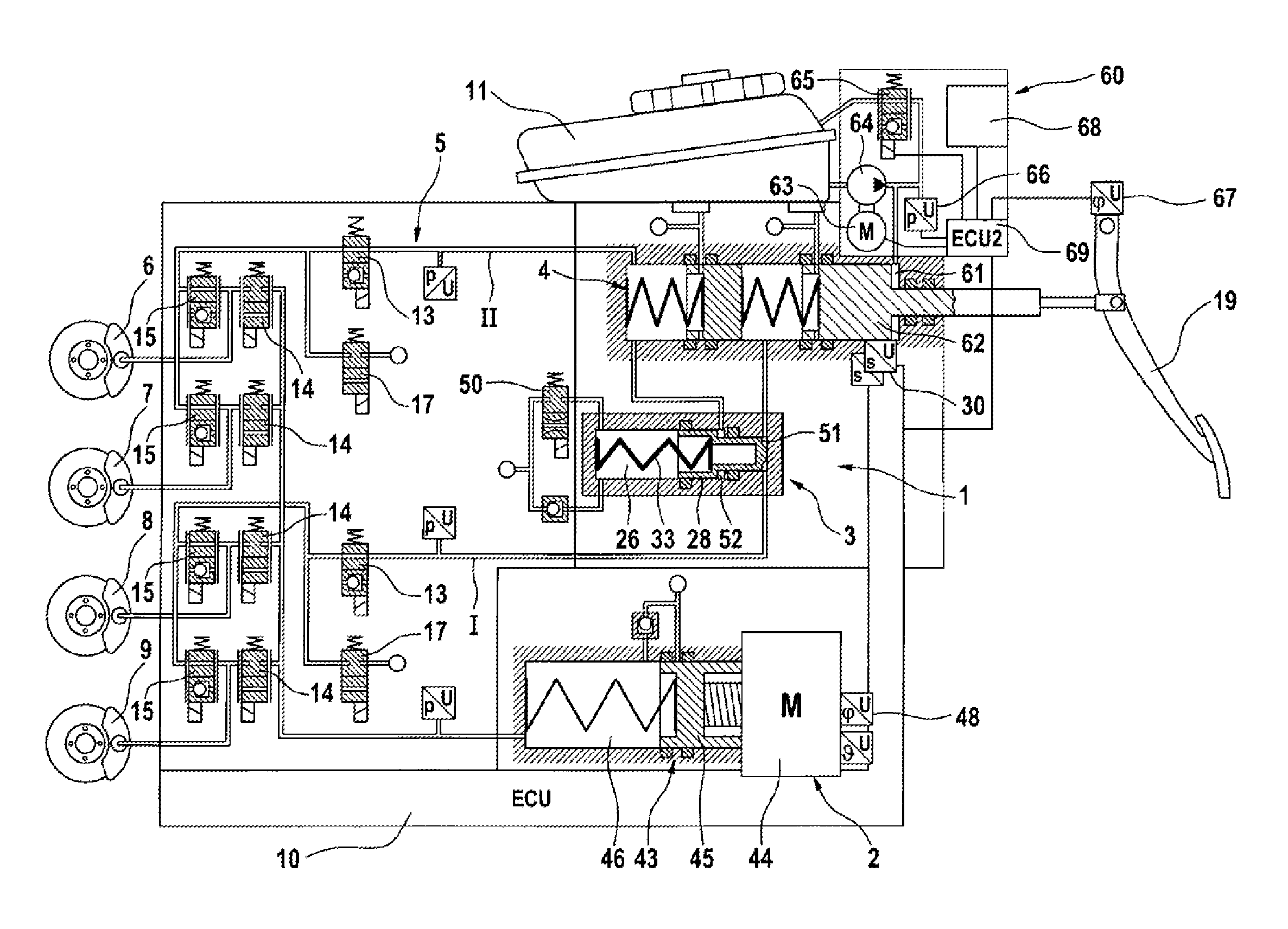
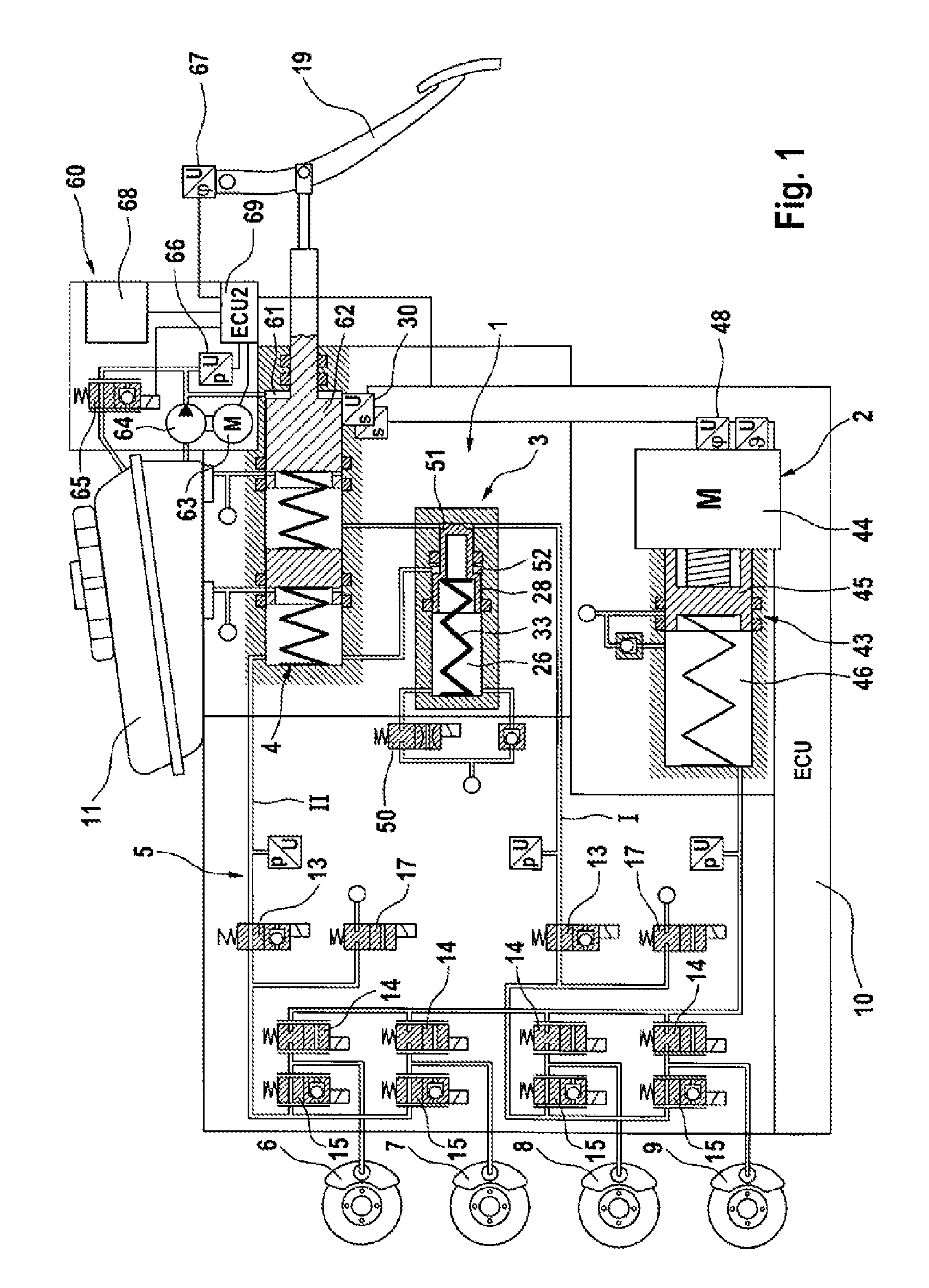
[0024]The embodiment example of a brake system according to the invention as shown in FIG. 1 and is described in more detail below. The electro-hydraulic brake system shown as an example in the FIGURE substantially comprises an actuator device 1 with a tandem brake master cylinder 4 and a simulation device 3, an electrically controllable pressure-generating device 2, a wheel brake pressure modulation device or pressure-regulating valve arrangement 5, and an electronic control and regulating unit (ECU) 10. Wheel brakes 6, 7, 8, 9 are connected to the wheel-brake-pressure modulation device 5. The pressure chambers of the brake master cylinder 4 can be connected with a pressure medium storage reservoir 11 under atmospheric pressure. The wheel brakes 6, 7, 8, 9 are allocated to the brake circuits I, II such that the wheel brakes 8, 9 connected to the first brake circuit I are allocated to one vehicle axle while the wheel brakes 6, 7 connected to the second brake circuit II serve to brak...


PUM


Abstract

A brake system for motor vehicles comprising a brake master cylinder which can be activated by means of a brake pedal and to which wheel brakes are connected. The brake system also comprises an electrically controllable pressure-generating device, a pressure-regulating valve arrangement to regulate a wheel brake pressure set at a wheel brake, a first electronic control and regulating unit which controls at least one of the pressure-generating device, the pressure-regulating valve arrangement, and an electrically controllable auxiliary pressure-generating device by means of which the brake master cylinder can be activated by means of which a pressure in an intermediate chamber of the brake master cylinder can be controlled or regulated.

Description

CROSS-REFERENCE TO RELATED APPLICATIONS[0001]This application claims priority to German Patent Application Numbers 10 2010 039 931.0, filed Aug. 30, 2010, 10 2011 081 461.2, filed Aug. 24, 2011, and PCT / EP2011 / 064595, filed Aug. 25, 2011.FIELD OF THE INVENTION[0002]The invention concerns a brake system for motor vehicles with a brake master cylinder which can be activated by means of a brake pedal and to which wheel brakes are connected, an electrically controllable pressure-generating device. The system further having a pressure-regulating valve arrangement to regulate and / or control a wheel brake pressure set at a wheel brake, and a first electronic control and regulating unit which controls or regulates the pressure-generating device and / or the pressure-regulating valve arrangement.BACKGROUND AND INTRODUCTORY DESCRIPTION OF THE INVENTION[0003]In automotive technology, “brake by wire” brake systems are becoming increasingly common. Such brake systems often comprise a pedal-decoupl...

Claims


Application Information

Patent Timeline
IPC IPC(8): B60T13/74B60T7/06
CPCB60T7/042B60T8/4081B60T8/441B60T11/20B60T13/662B60T13/745B60T17/18B60T2270/402B60T2270/82B60T7/06B60T13/686B60T7/04B60T13/68
Inventor LINKENBACH, STEFANDRUMM, STEFAN
Owner CONTINENTAL TEVES AG & CO OHG
Why Eureka
Try Eureka