Spindle motor

a spindle motor and spindle motor technology, applied in the field of spindle motors, can solve the problems of difficult to obtain position accuracy and mass production of spindle motors, difficult to re-use high-priced circuit boards, and difficulty in obtaining reliability in environmental tests, etc., to achieve the effect of inhibiting alignment defects

Inactive Publication Date: 2013-06-13
HITACHI LG DATA STORAGE KOREA
View PDF18 Cites 1 Cited by
  • Summary
  • Abstract
  • Description
  • Claims
  • Application Information

AI Technical Summary

Benefits of technology

[0011]The present invention provides a spindle motor configured to accurately align a base plate and a circuit boa

Problems solved by technology

However, the coupling of the base plate to the circuit board using the double-sided tape in a conventional spindle motor requires a complex assembly process, and provides a difficulty in obtaining reliability in an environmental test under high temperature high humidity circumstances.
Furthermore, accurate and simultaneous assembly of base plate, double-sided tape and circuit board at a designated position make it difficult to obtain position accuracy and to mass-produce spindle motors.
On top of that, in a case the double-sided tape has a high bonding strength, it is difficult to re-use a high-priced circuit board due to high strength of a

Method used


Image

  • Spindle motor
  • Spindle motor
  • Spindle motor

Examples


first exemplary embodiment

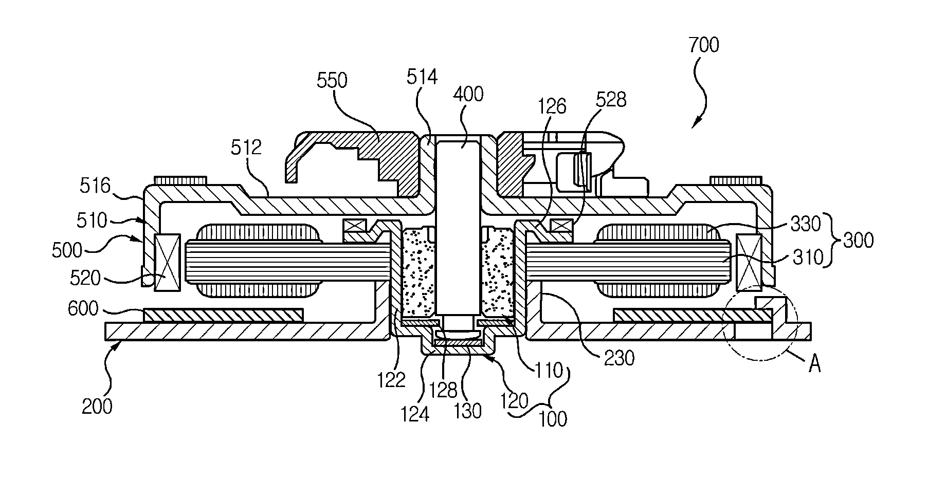
[0028]FIG. 1 is a cross-sectional view of a spindle motor (700) according to an exemplary embodiment of the present disclosure.

[0029]Referring to FIG. 1, the spindle motor (700) includes a bearing assembly (100), a stator (300), a rotation shaft (400), a rotor (500), a base plate (200) and a circuit board (600).

[0030]The bearing assembly (100) includes a bearing (110) and a bearing housing (120). The bearing (110) takes a shape of a circular cylinder having an outer surface and an inner surface opposite to the outer surface. The bearing (110) in an exemplary embodiment of the present disclosure may include an oil-impregnated sintered bearing. The inner surface of the bearing (110) is formed by a rotation shaft hole with an equal diameter, and rotationally supports the rotation shaft (400, described later).

[0031]The bearing housing (120) takes a shape of an upper surface-opened cylinder, and includes a lateral plate (122) and a floor plate (124). In addition, the bearing housing (120...

second exemplary embodiment

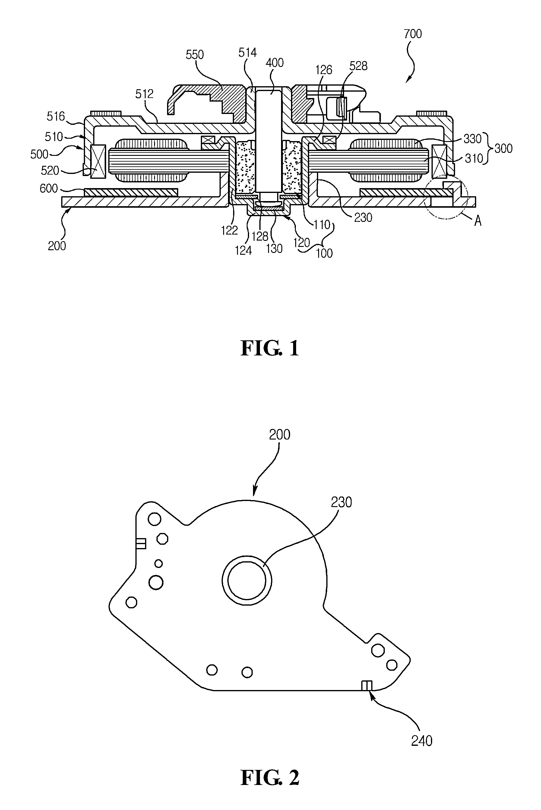
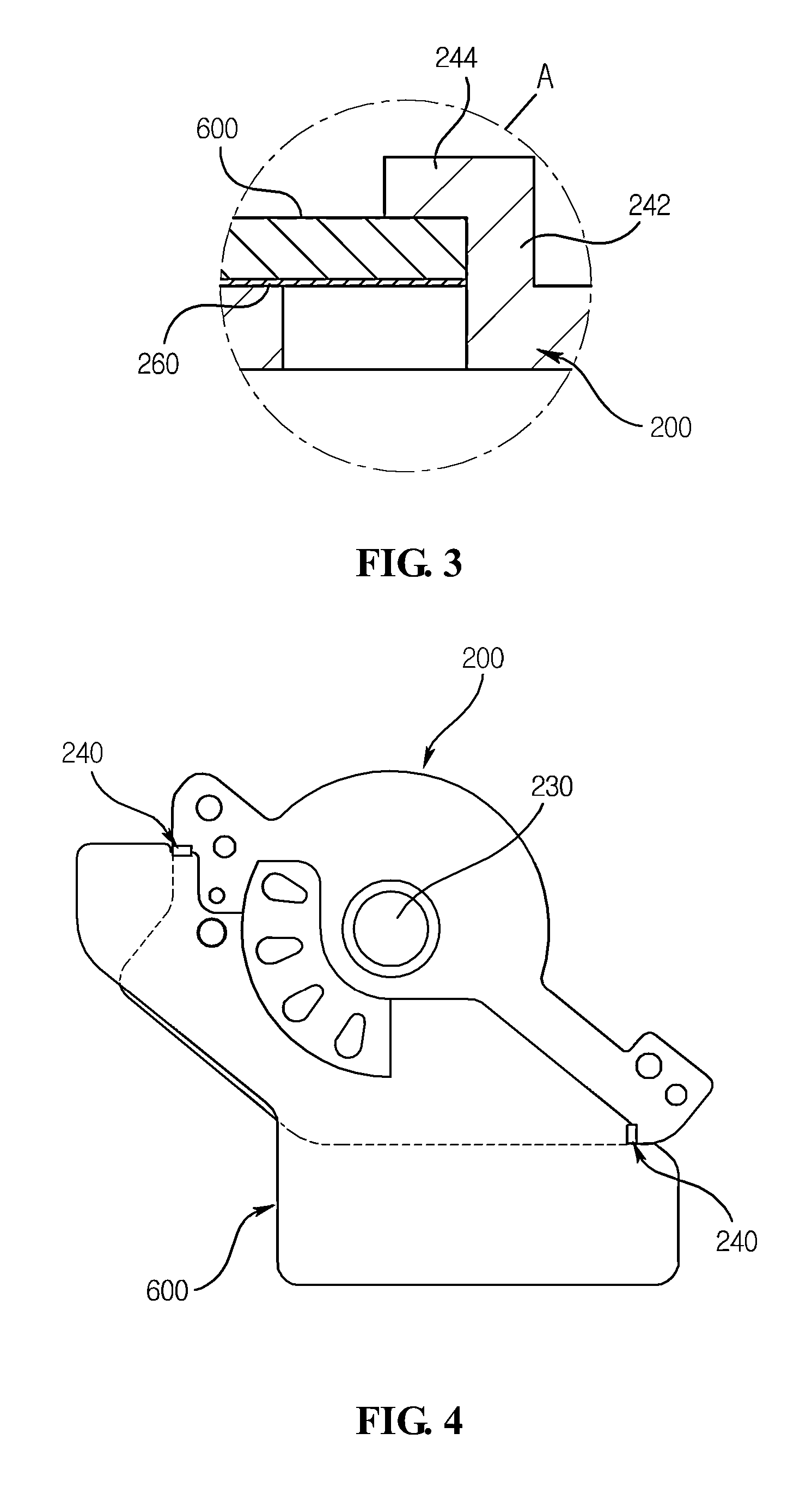
[0050]FIG. 7 is a plane view of a base plate of FIG. 1, and FIG. 8 is a cross-sectional view of an alignment unit cut along line ‘I-I’ of FIG. 7.

[0051]Referring to FIGS. 1, 7 and 8, a base plate (200) is fixed to an outer surface of a bearing housing (120) through a distal end of a bottom surface of the bearing housing (120) opposite to an upper distal end of the bearing housing (120) formed with a flange unit (126). The base plate (200) includes a burring unit (230) for fixing an outer surface of the bearing housing (120).

[0052]Meanwhile, the base plate (200) is also formed with at least two alignment units (210) each spaced apart at a predetermined distance. The alignment unit (210) serves to accurately align the circuit board (600, described later) and the base plate (200). At least two alignment units (210) are formed at the base plate (200), and each of the alignment units (210) is formed at a position spaced apart from the other at a predetermined distance. The alignment unit ...


PUM


Abstract

A spindle motor is provided, the motor including a bearing assembly including a bearing housing accommodating a bearing, a stator coupled to an ambience of the bearing housing, a rotation shaft rotatably accommodated into the bearing, a rotor coupled to the rotation shaft to rotate in association with the stator, a base plate coupled to the bearing housing, and a circuit board arranged at an upper surface of the base plate to be electrically connected to the stator.

Description

CROSS-REFERENCE TO RELATED APPLICATIONS[0001]This application claims the benefit under 35 U.S.C. §119 of Korean Patent Application Nos. 10-2011-0132680, filed Dec. 12, 2011, and 10-2011-0132683, filed Dec. 12, 2011, which are hereby incorporated by reference in their entirety.BACKGROUND[0002]The present disclosure generally relates to a spindle motor.[0003]An ODD (Optical Disk Drive) includes a spindle motor rotating an optical disk at a high speed, an optical pickup reading data from an optical disk or recording data on the optical disk, and a stepping motor moving an optical pickup module to a radial direction of a disk.[0004]The spindle motor includes a bearing assembly including a bearing and a bearing housing, a stator fixed to the bearing housing and a rotor coupled to a rotation shaft inserted into the bearing. Furthermore, the spindle motor includes a base plate fixing the bearing housing, and a circuit board arranged on an upper surface of the base plate and electrically co...

Claims


Application Information

Patent Timeline
IPC IPC(8): H02K11/00H02K5/16
CPCH02K11/0068H02K5/165G11B19/2009H02K1/187H02K5/1675H02K21/22H02K2211/03H02K11/30
Inventor KIM, CHAN SEOK
Owner HITACHI LG DATA STORAGE KOREA
Why Eureka
Try Eureka