Automatic Tuning Method for Energy Storage System of Railway Vehicle

a technology of energy storage system and automatic tuning, which is applied in the direction of ac network load balancing, secondary cell servicing/maintenance, transportation and packaging, etc. it can solve the problems of increasing oil price, increasing oil consumption, and increasing natural resources such as fossil fuel energy in the world, so as to achieve the stabilization of overhead line voltage, optimize energy saving effect, and efficiently use regenerative energy

Inactive Publication Date: 2013-06-13
LEE EUN KYU +2
View PDF3 Cites 25 Cited by
  • Summary
  • Abstract
  • Description
  • Claims
  • Application Information

AI Technical Summary

Benefits of technology

[0024]The automatic tuning method based on the energy storage system for railway trains according to the present invention has a variety of advantages. For example, it is possible to achieve optimal energy saving effects using a bidirectional DC/DC converter which can efficiently use regenerative energy of DC urban railways and can accomplish stabilization of overhead line v

Problems solved by technology

The worldwide industrialization has rapidly increased the oil consumption.
To make the matter worse, the natural resources, such as the fossil fuel energy in the world is becoming depleted.
Thus, the depletion of the natural resources is caused to raise the oil price steeply.
Such regenerated power instantaneously applies high voltage to the overhead line, causing variation in overhead line voltage.
This may not only make the system unstable but may also cause a malfunction of a subsequent train when the subsequent train cannot deal with such a high voltage.
However, it is difficult to efficiently utilize the system due to changes in overhead line voltage according to train operation and changes in subway substation output voltage.
However, it is very difficult to set a discharging start voltage, a

Method used


Image

  • Automatic Tuning Method for Energy Storage System of Railway Vehicle
  • Automatic Tuning Method for Energy Storage System of Railway Vehicle
  • Automatic Tuning Method for Energy Storage System of Railway Vehicle

Examples


Embodiment Construction

[0033]Embodiments of the present invention will now be described in detail with reference to the drawings.

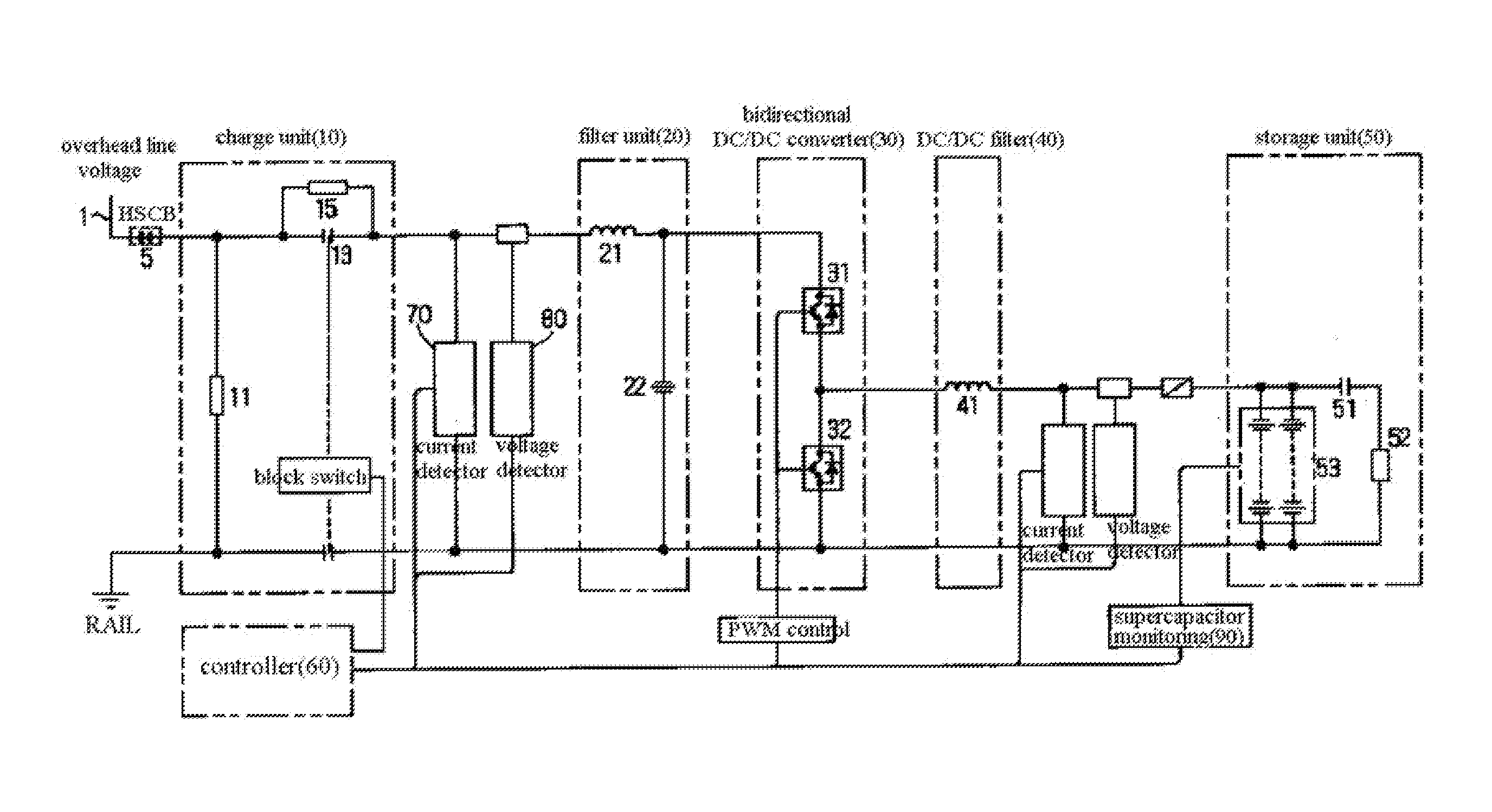
[0034]FIG. 3 is a circuit diagram of an energy storage apparatus for railway trains according to an embodiment of the present invention.

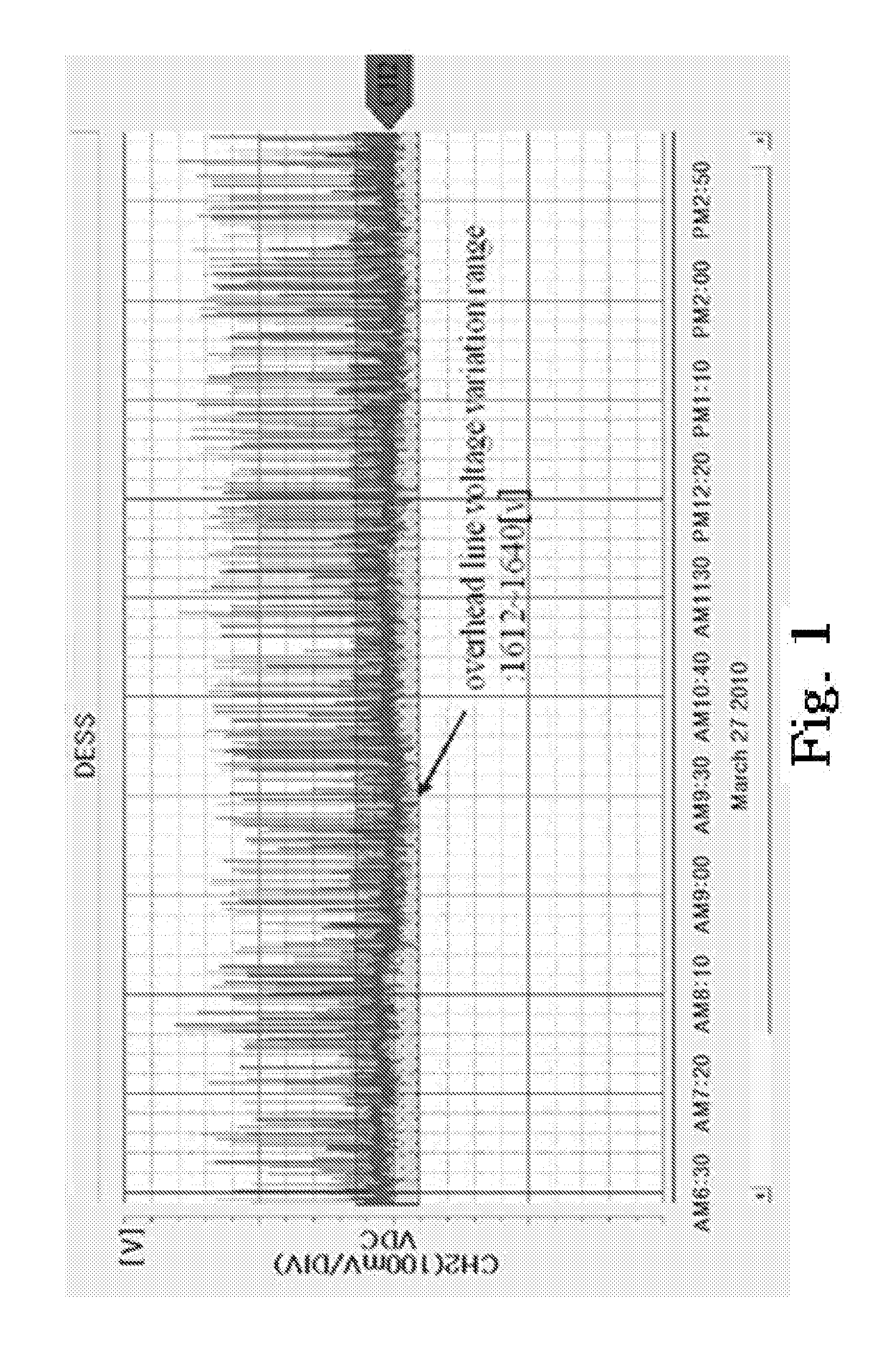
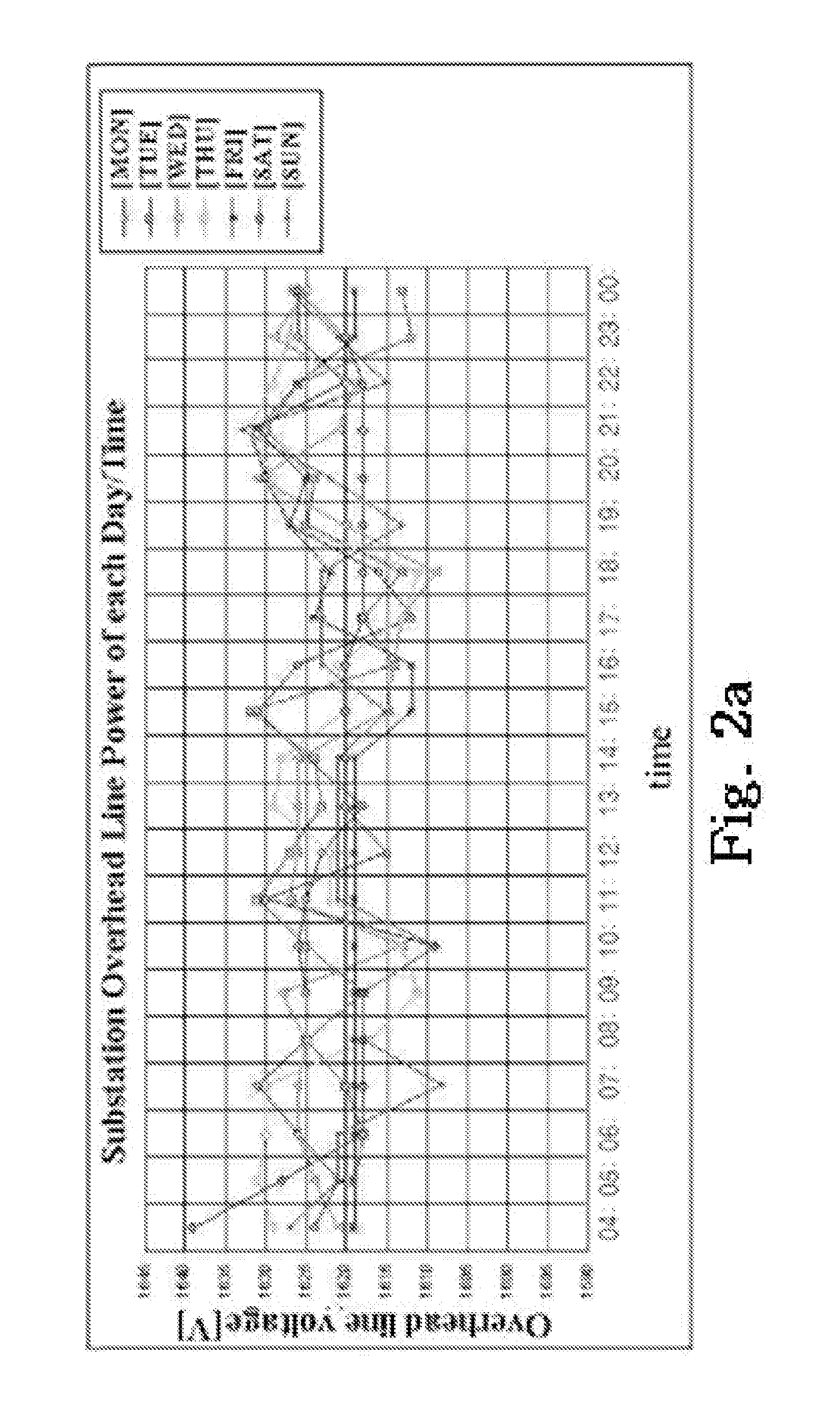
[0035]In an automatic tuning method based on an energy storage system for railway trains according to the embodiment of the present invention, optimal tracking of changes in overhead line voltage, which varies with time and according to substation voltage variation and a train operation pattern, is automatically performed to maximize energy storage efficiency.

[0036]Hereinafter, an electric dual layer capacitor is referred to as an EDLC for short.

[0037]The energy storage apparatus according to a preferred embodiment of the present invention includes a charging unit 10, a filter unit 20, a bidirectional DC / DC converter 30, a DC / DC filter 40, a storage unit 50, a controller 60, a current detector 70, and a voltage detector 80.

[0038]Since the bidire...


PUM


Abstract

An automatic tuning method is developed for an energy storage system of the railway vehicle. The method comprises; an optimal tracking for voltage fluctuation in the overhead line voltage varying with hourly-basis, the voltage variation of the substation and railway vehicle operating pattern. The railway vehicle is automatically performed the tuning to maximize the energy storing efficiency. The railway vehicle can achieve the optimum operation for saving energy effectively by bidirectional DC/DC converter using regenerative energy of DC. The railway vehicle stably operates under the overhead line voltage fluctuation. The energy efficiency is maximized by charging/discharging energy while the power is tracking unstable, which is generated by utilizing natural energies such as wind or solar energy, in real time by applying an automatic tuning algorithm to an energy storage system which is applied to a smart grid or a micro grid that uses renewable energy as a primary energy source.

Description

BACKGROUND OF THE INVENTION[0001]1. Field of the Invention[0002]The present invention relates to an automatic tuning method for an energy storage system of the railway vehicle. More particularly, the railway vehicle performs the automatic tuning for optimum operation, while it is undergoing the voltage fluctuation of the substations, the voltage variations due to the traffic volume, the wire voltage fluctuation due to the demand variation of power on the hourly basis. The energy storage system of the railway vehicle is designed to be maximizing in the efficiency of operation and maximizing the energy storing capacity.[0003]2. Related Prior Art[0004]The worldwide industrialization has rapidly increased the oil consumption. As a result, our environment has changed. Due to increase the pollutants in our environment, the world's climate has rapidly warmed. To make the matter worse, the natural resources, such as the fossil fuel energy in the world is becoming depleted. Thus, the depleti...

Claims


Application Information

Patent Timeline
IPC IPC(8): H02J7/00
CPCB60L9/005B60L2210/10B60L2200/26H02J3/28Y02T10/7216H02J2310/40Y02T10/72Y02E60/10B60M3/02B60L9/18H02J7/04H01M10/44
Inventor LEE, EUN-KYUKIM, TAE-SUKKWON, KYOUNG-MIN
Owner LEE EUN KYU
Why Eureka
Try Eureka