Zero voltage switching in flyback converters with variable input voltages

a technology of input voltage and zero voltage, which is applied in the field of power converters, can solve the problems of reducing the efficiency affecting the efficient and/or safe operation and the temperature of the flyback converter to approach and/or exceed, so as to reduce the power loss of the flyback converter

Active Publication Date: 2013-06-13
APPLE INC
View PDF8 Cites 57 Cited by
  • Summary
  • Abstract
  • Description
  • Claims
  • Application Information

AI Technical Summary

Benefits of technology

[0016]In some embodiments, the negative peak current reduces the power loss of the flyback converter by reducing at least one of a switching loss of the primary switch and a conduction loss associated with the flyback converter.

Problems solved by technology

Power losses in a flyback converter may include conduction losses caused by the conduction of current within the components (e.g., transformers, switches, etc.) of the flyback converter, as well as switching losses resulting from the switching of diodes and / or metal-oxide-semiconductor field-effect transistors (MOSFETs) in the flyback converter.
Such power losses may reduce the efficiency of the flyback converter, and in turn, generate heat that causes the temperature of the flyback converter to approach and / or exceed the peak operating temperature for the flyback converter.
Consequently, power losses in the flyback converter may adversely affect the efficient and / or safe operation of the flyback converter.
As a result, ZVS techniques may generate additional power losses if the flyback converters are operated with input voltages for which the ZVS techniques are not configured.
Use of high-line ZVS with a low-line input voltage may thus produce additional current in the flyback converter, which increases the conduction losses within the flyback converter without reducing the switching loss of the primary MOSFET.

Method used


Image

  • Zero voltage switching in flyback converters with variable input voltages
  • Zero voltage switching in flyback converters with variable input voltages
  • Zero voltage switching in flyback converters with variable input voltages

Examples


Embodiment Construction

[0023]The following description is presented to enable any person skilled in the art to make and use the embodiments, and is provided in the context of a particular application and its requirements. Various modifications to the disclosed embodiments will be readily apparent to those skilled in the art, and the general principles defined herein may be applied to other embodiments and applications without departing from the spirit and scope of the present disclosure. Thus, the present invention is not limited to the embodiments shown, but is to be accorded the widest scope consistent with the principles and features disclosed herein.

[0024]The data structures and code described in this detailed description are typically stored on a computer-readable storage medium, which may be any device or medium that can store code and / or data for use by a computer system. The computer-readable storage medium includes, but is not limited to, volatile memory, non-volatile memory, magnetic and optical...


PUM


Abstract

The disclosed embodiments provide a system that operates a flyback converter. During operation, the system senses an input voltage for the flyback converter. Next, the system uses the input voltage to determine a negative peak current that enables zero voltage switching for a primary switch in the flyback converter. Finally, the system uses the negative peak current to perform the zero voltage switching for the primary switch based on the input voltage, wherein the negative peak current reduces a power loss of the flyback converter.

Description

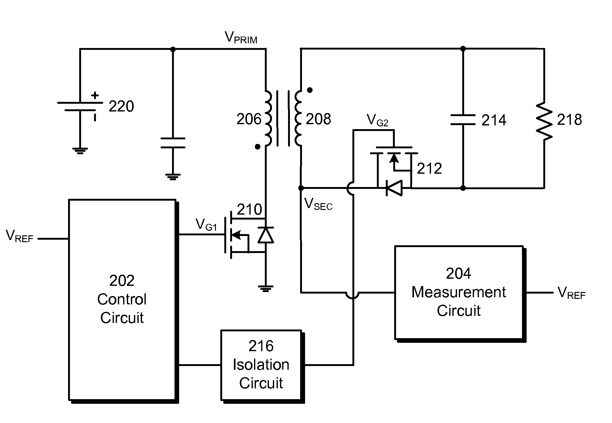
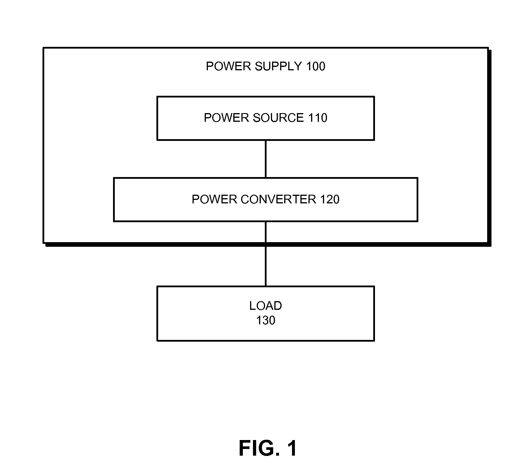
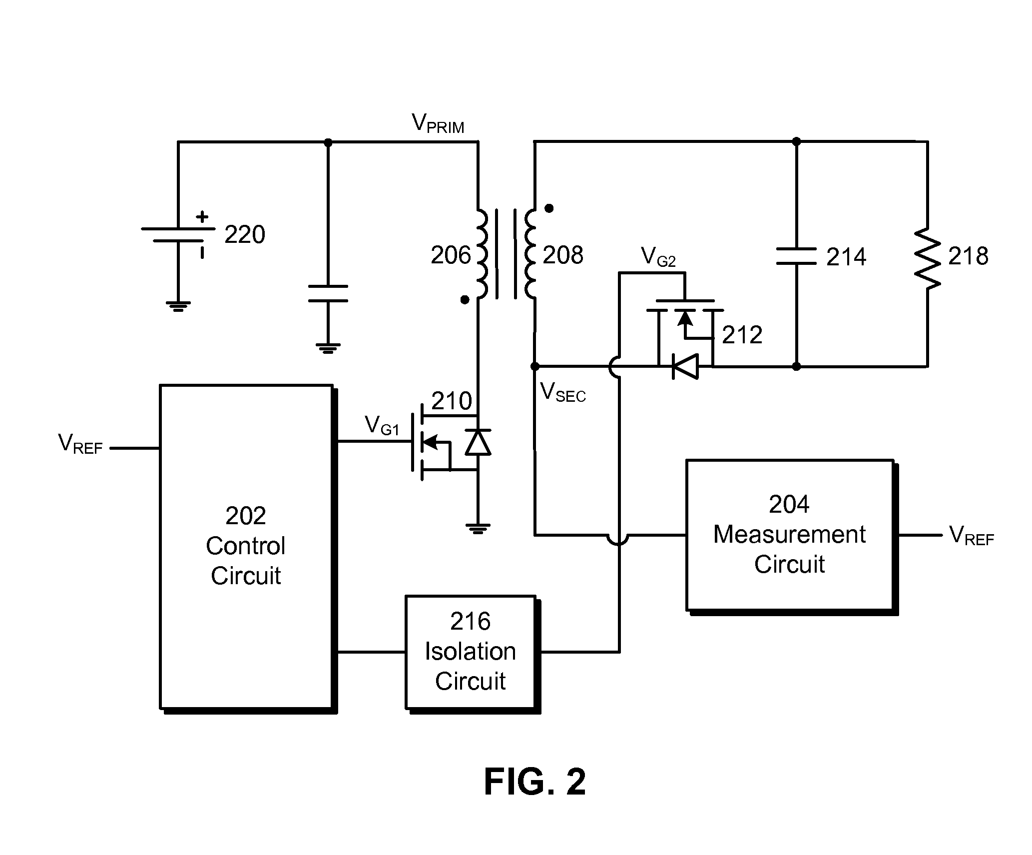
BACKGROUND[0001]1. Field[0002]The present embodiments relate to power converters for electronic devices. More specifically, the present embodiments relate to techniques for performing zero voltage switching in flyback converters with variable input voltages.[0003]2. Related Art[0004]Flyback converters may be used to convert alternating current (AC) to direct current (DC) in low-power applications such as mobile phone chargers and / or laptop computer power adaptors. For example, an external power supply (e.g., power brick) for a laptop computer may use a flyback converter to convert AC mains power from a power outlet into low-voltage DC that can be used by components in the laptop computer.[0005]Power losses in a flyback converter may include conduction losses caused by the conduction of current within the components (e.g., transformers, switches, etc.) of the flyback converter, as well as switching losses resulting from the switching of diodes and / or metal-oxide-semiconductor field-e...

Claims


Application Information

Patent Timeline
Patent Type & Authority Applications(United States)
IPC IPC(8): H02M3/335
CPCY02B70/1475H02M3/33592Y02B70/10
Inventor ZHANG, XIAOYANG
Owner APPLE INC
Why Eureka
Try Eureka