Method and Optical Line Terminal for Optical Fiber Fault Diagnosis in Passive Optical Network

a technology of optical fiber and fault diagnosis, applied in the field of optical access network, can solve the problems of complex structure, lack of maintainability of test results, and inability to improve the weaknesses existing in traditional test methods, so as to improve the reliability of the system, reduce the operating cost of the network, and simplify the system network structure

Inactive Publication Date: 2013-06-13
ZTE CORP
View PDF43 Cites 18 Cited by
  • Summary
  • Abstract
  • Description
  • Claims
  • Application Information

AI Technical Summary

Benefits of technology

[0005]The technical problem required to be solved by the present invention is to provide a method for performing optical fiber fault diagnosis in a Passive Optical Network (PON) and an optical line terminal, and the Optical Time Domain Reflectometer (OTDR) technology is applied in PON Optical Line Terminal (OLT) design, which makes a PON device have an ability of optical fiber fault diagnosis in itself and simplifies a networking structure of the system.
[0040]In conclusion, with the method for performing optical fiber fault diagnosis in the passive optical network and the optical line terminal provided by the present invention, firstly, the process of optical fiber fault diagnosis is performed in combination with a PON network management system, which satisfies the requirements of timeliness and maintainability; furthermore, the OTDR technology is applied in the PON OLT design, which makes a PON network device possess the ability of optical fiber fault diagnosis in itself and simplifies the networking structure of the system, and meanwhile, it is not required to introduce other devices or components besides the OTDR component in the method of the present invention, which decreases operating costs of the network; in addition, with the method of the present invention, the optical fiber fault diagnosis within each OLT domain is carried out independently, which enhances the reliability of the system; it also can utilize uplink management channels of the PON system to report fault conditions within each OLT domain to the upper layer network management for performing centralized processing, which improves the manageability and maintainability of fault information in the PON system.

Problems solved by technology

At present, though using the OTDR equipment to perform optical fiber fault diagnosis in the PON network has no technical difficulty, inherent weaknesses existing in this traditional test means have not been improved yet.
The fundamental form of optical fiber fault diagnosis of the traditional PON is that an OTDR fault diagnosis equipment is independent from the PON network, and after faults occur in the network, a tester makes the OTDR equipment access the PON network to complete the test; the starting process of the test lacks the timeliness (wherein, the timeliness means that the test can be started timely after the software discovers the faults, and the software is controllable); meanwhile, test results also lacks the maintainability.
This method can satisfy the timeliness and maintainability of the fault diagnosis, but the networking structure is complicated and the introduction of devices such as the optical switch and so on also increases operating costs of the network.
Meanwhile, when an OTDR equipment at the office end tests a great many PON OLT optical fiber lines, once the meter breaks down, tests of multiple PON networks will be influenced, and hidden troubles exist in the aspect of reliability.

Method used


Image

  • Method and Optical Line Terminal for Optical Fiber Fault Diagnosis in Passive Optical Network
  • Method and Optical Line Terminal for Optical Fiber Fault Diagnosis in Passive Optical Network
  • Method and Optical Line Terminal for Optical Fiber Fault Diagnosis in Passive Optical Network

Examples


Embodiment Construction

[0051]In order to better understand the present invention, the present invention will be further described in combination with the accompanying drawings and specific examples below. It should be noted that the examples in the present invention and the characteristics in the examples can be optionally combined with each other in the condition of no conflict.

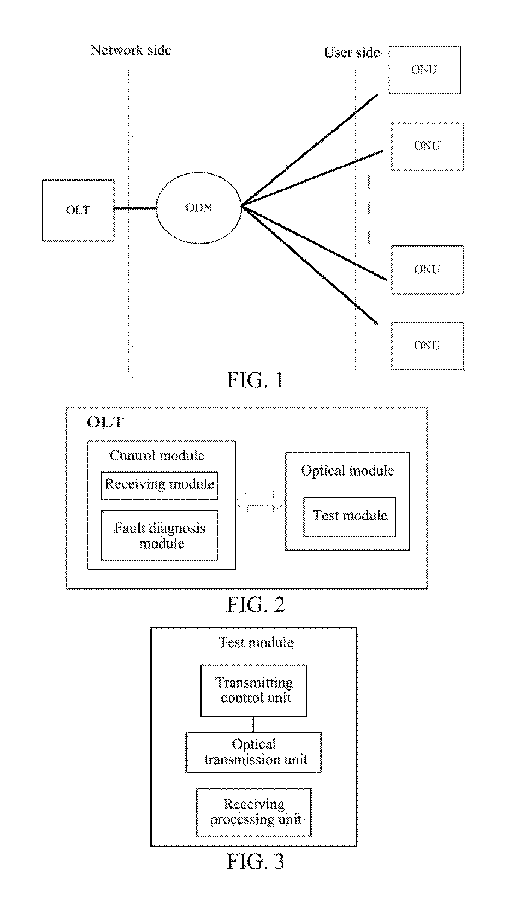
[0052]FIG. 2 is a schematic diagram of an optical line terminal according to the present invention, and as shown in FIG. 2, the optical line terminal of the example includes: a control module and an optical module. The control module is used for service processing and system management of the optical line terminal, which includes controlling the optical module to send and receive serviced, wherein, the control module includes a receiving module and a fault diagnosis module and has a function of control management and data analysis for a test module of an optical time domain reflectometer, and the optical module includes a test mod...


PUM


Abstract

A method for performing optical fiber fault diagnosis in a passive optical network is disclosed in the present invention. The method includes: after receiving an optical fiber fault diagnosis message, a receiving module of an optical line terminal triggering a test module (S10); after triggered by the receiving module, the test module performing an optical time domain reflection test, and obtaining data information (S20) of the test; and a fault diagnosis module analyzing the data information, and performing optical fiber fault diagnosis (S30). An optical line terminal is also disclosed in the present invention, including a control module and an optical module, and the control module includes a receiving module and a fault diagnosis module, and the optical module includes a test module. In the present invention, the process of optical fiber fault diagnosis is performed in combination with PON network management system.

Description

TECHNICAL FIELD[0001]The present invention relates to the field of optical access network, and specifically, to a method for applying the Optical Time Domain Reflectometer (OTDR) technology to perform optical fiber fault diagnosis in a passive optical network, and an optical line terminal.BACKGROUND OF THE RELATED ART[0002]With the mature development of the optical fiber communication technology and the continuous promotion of the service demands of three-network convergence, Fiber To The Home (FTTH) has undoubtedly become an ultimate approach to solve the bottleneck problem of bandwidths of access network, and the technique of Passive Optical Network (PON) is widely popular due to its advantages such as high bandwidth, remote transmission and point-to-multipoint topology and so on, and it has become a major application architecture for every country deploying the FTTH. The PON is a passive optical access technology by using the point-to-multipoint topology structure, and the topolo...

Claims


Application Information

Patent Timeline
Patent Type & Authority Applications(United States)
IPC IPC(8): H04B10/071H04B10/272
CPCH04B10/272H04B10/071
Inventor LIANG, WEILU, JIANXIN
Owner ZTE CORP
Why Eureka
Try Eureka