Bearing Assembly For A Solar Collector System

a technology of solar collector and bearing assembly, which is applied in the direction of mechanical equipment, light and heating equipment, other domestic objects, etc., can solve the problems of low energy conversion efficiency, high capital cost, and vast untapped renewable energy sources of solar energy

Inactive Publication Date: 2013-06-20
MAGNA INTERNATIONAL INC
View PDF5 Cites 8 Cited by
  • Summary
  • Abstract
  • Description
  • Claims
  • Application Information

AI Technical Summary

Benefits of technology

[0015]In accordance with an aspect of the invention there is provided a solar collector system, comprising: a movable solar collector surface; a cylindrical support element coupled to the solar collector surface, the cylindrical support element having an outer surface extending along a length thereof and being rotatable about a longitudinal axis defined along said length; a housing assembly comprising a plurality of spherical rollers, the housing assembly coupled to the cylindrical support element such that the cylindrical support element is disposed between a first group of the plurality of spherical rollers and a second group of the plurality of spherical rollers, the housing assembly comprising

Problems solved by technology

In particular, solar energy is known to be a vast and largely untapped renewable energy source that can be converted into a usable form without releasing harmful emissions into the environment.
Unfortunately, high capital costs combined with low energy conversion efficiencies have thus far limited the adoption of solar collector systems to mostly small-scale installations and “off-grid” or niche applications.
Unfortunately, the methods and apparatus for supporting and aiming solar collectors toward the sun are rather crude and simple.
This-type of apparatus for supporting the solar collector is wrought with many problems.
Specifically, it is extremely difficult to install such a type of system in such a manner that the bearing structures and the support rods are in precise alignment.
Of course, even if the collector system is installed with the bearing structures precisely aligned to receive the support rods, problems still arise due to an uneve

Method used


Image

  • Bearing Assembly For A Solar Collector System
  • Bearing Assembly For A Solar Collector System
  • Bearing Assembly For A Solar Collector System

Examples


Embodiment Construction

[0024]The following description is presented to enable a person skilled in the art to make and use the invention, and is provided in the context of a particular application and its requirements. Various modifications to the disclosed embodiments will be readily apparent to those skilled in the art, and the general principles defined herein may be applied to other embodiments and applications without departing from the scope of the invention. Thus, the present invention is not intended to be limited to the embodiments disclosed, but is to be accorded the widest scope consistent with the principles and features disclosed herein.

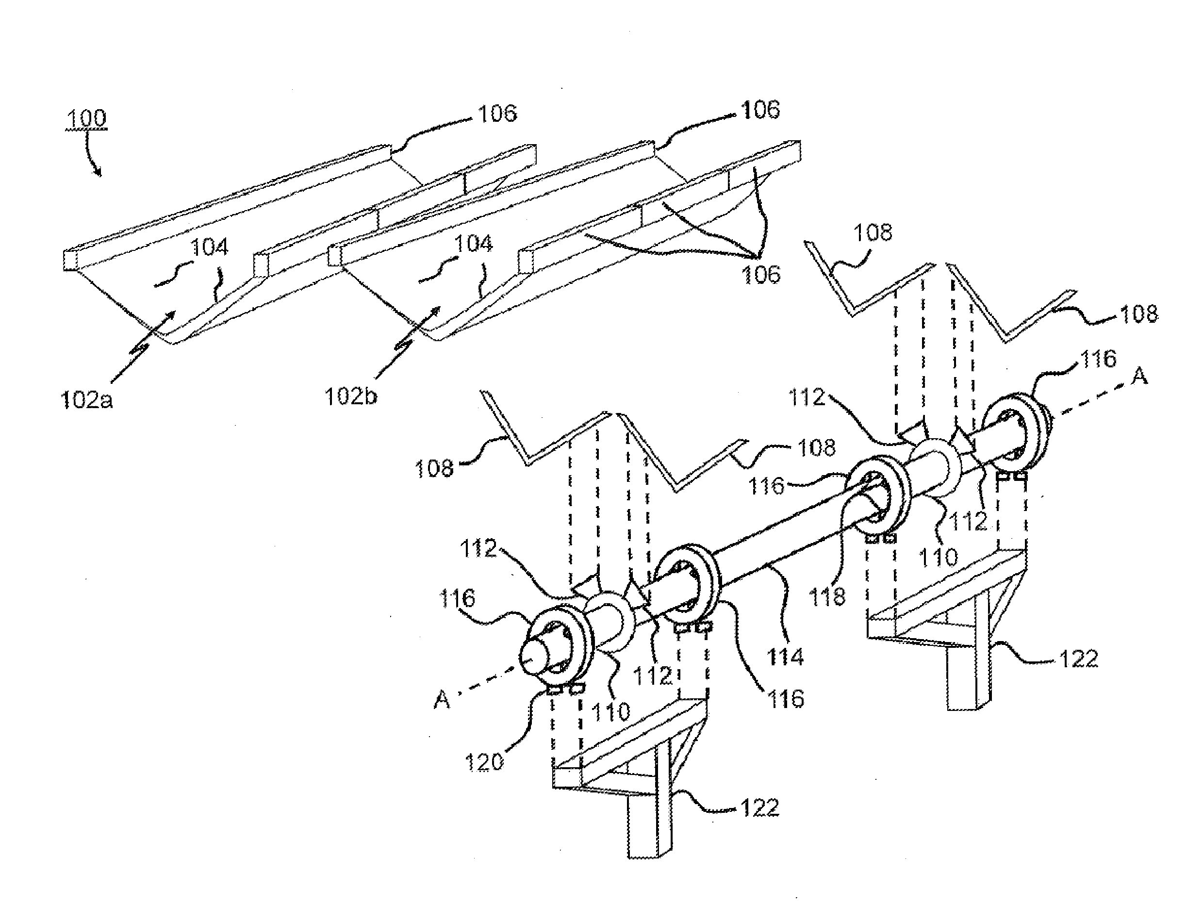
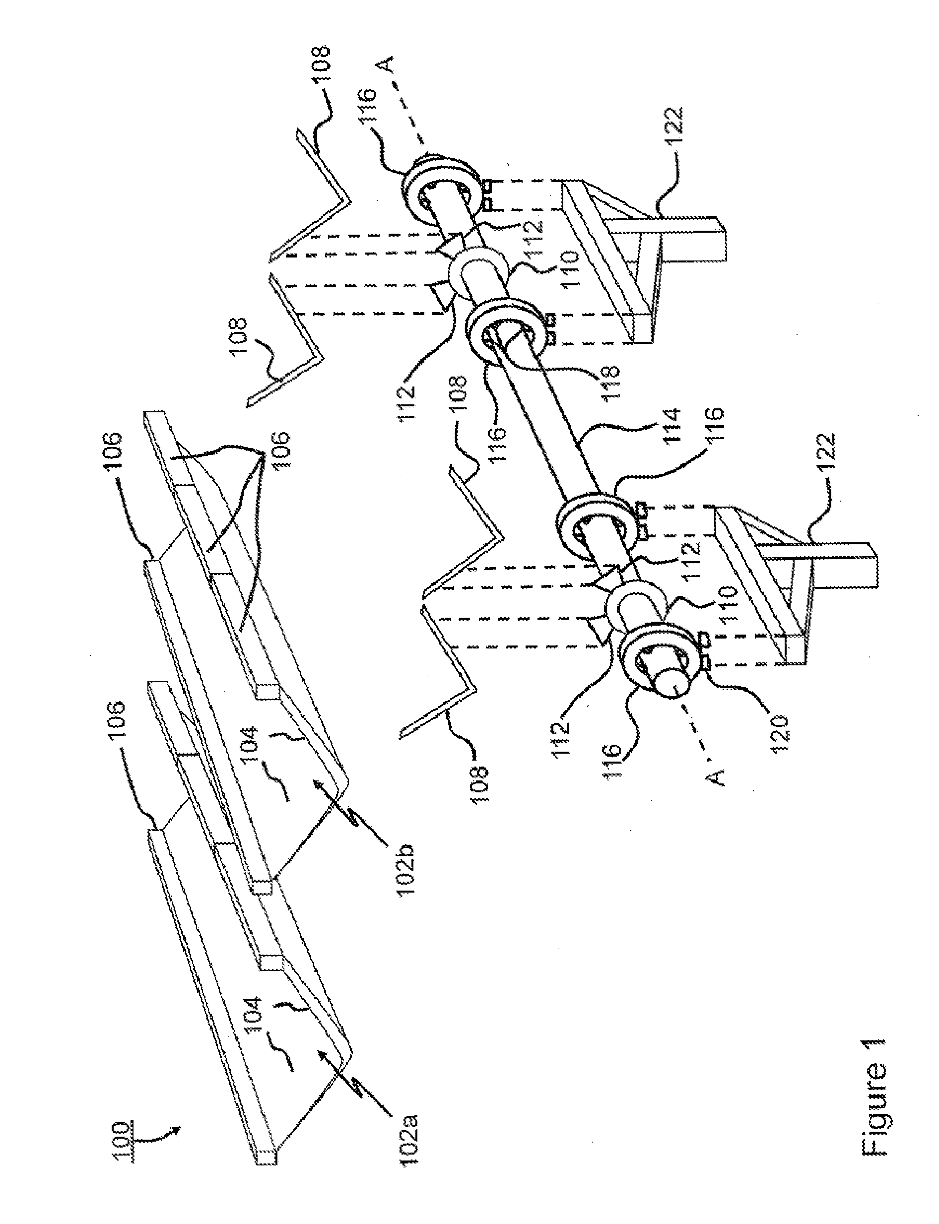
[0025]Referring to FIG. 1, shown is an exploded perspective view of a solar collector assembly 100 according to an embodiment of the instant invention. In this specific and non-limiting example the collector assembly 100 is a dual trough solar energy concentrator or collector, having two optical apertures 102a and 102b. The optical apertures 102 admit incident ...


PUM

PropertyMeasurementUnit
Timeaaaaaaaaaa
Angleaaaaaaaaaa
Angleaaaaaaaaaa

Abstract

A solar collector system is provided including a bearing assembly comprising a plurality of wheels or rollers for rollingly engaging a large-diameter support element. Rotation of the large-diameter support element supports tracking of the position of the sun relative to the solar collector system. The bearing assembly may be pre-assembled to the large-diameter support element before the solar collector system leaves the factory, thereby facilitating assembly of the solar collector system in the field, even under adverse conditions.

Description

CROSS REFERENCE TO RELATED APPLICATIONS[0001]This U.S. National Stage Patent Application claims the benefit of International Application serial number PCT / US11 / 42442 filed Jun. 29, 2011 and U.S. provisional application Ser. No. 61 / 360,612 filed Jul. 1, 2010, the entire disclosures of the applications being considered part of the disclosure of this application, and hereby incorporated by reference.BACKGROUND OF THE INVENTION[0002]1. Field of the Invention[0003]The instant invention relates generally to a bearing assembly for a solar collector system, and more particularly to a low speed bearing assembly for a solar collector system based on a large diameter structural support cylinder.[0004]2. Description of the Prior Art[0005]Systems that are designed to convert solar radiation or “solar energy” into heat or electricity have long been suggested as an attractive alternative to conventional energy sources such as crude oil, natural gas and the like. In particular, solar energy is know...

Claims


Application Information

Patent Timeline
IPC IPC(8): F24J2/54F24S23/70
CPCF16C19/50F24J2/541F24J2002/1023Y10T29/49355F24J2/54Y02E10/47F24J2002/5482F24S50/20F24S30/40F24S30/425F24S2023/834F24S2030/15Y02P80/20
Inventor MARTEN, ZACHARYKOTAGIRI, VIKAS
Owner MAGNA INTERNATIONAL INC
Why Eureka
Try Eureka