Top-emitting white organic light-emitting diodes having improved efficiency and stability

a technology of organic light-emitting diodes and top-emitting white colors, which is applied in the direction of organic semiconductor devices, solid-state devices, thermoelectric devices, etc., can solve the problems of affecting general lighting applications and the microcavity effect may be serious

Active Publication Date: 2013-06-20
NITTO DENKO CORP
View PDF6 Cites 19 Cited by
  • Summary
  • Abstract
  • Description
  • Claims
  • Application Information

AI Technical Summary

Benefits of technology

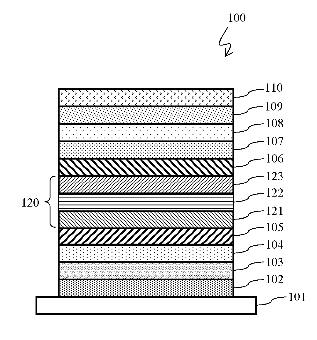
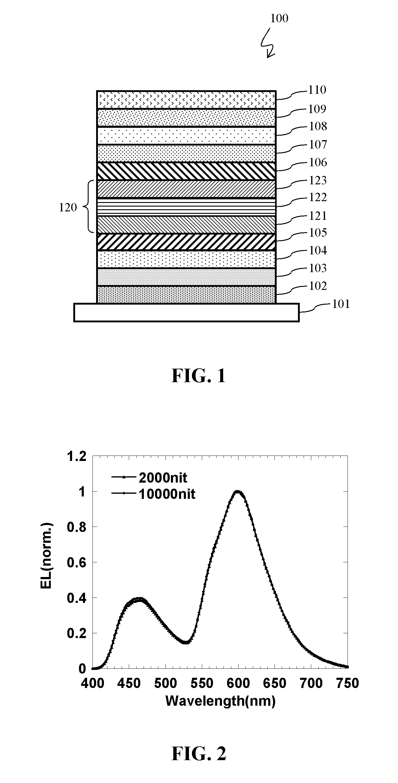
[0008]An embodiment provides an emissive construct, which can be used in various OLED applications, for example, top-emission white organic light-emitting diodes. In some embodiments, the emissive construct comprises a fluorescent emissive layer comprising a first host material, a partial hole-blocking layer having a first thickness disposed on the fluorescent emissive layer, and a phosphorescent emissive layer disposed on the partial hole-blocking layer, comprising a second host material. In some embodiments, a recombination zone is shared between the fluorescent emissive layer and the phosphorescent emissive layer. In some embodiments, the recombination zone has a second thickness, wherein the first thickness of the partial hole-blocking layer is less than about one-third of the second thickness of the recombination zone.

Problems solved by technology

For a semi-transparent top cathode, the microcavity effect may be serious due to a relatively higher reflectance of the metal semi-transparent cathode compared with a transparent ITO cathode.
While such a feature may be good for display applications, it can also negatively affect general lighting applications because white-color light emission is desired.
There are many challenging issues in TE-OLED manufacturing, including materials for the bottom reflective anode, the active cells of the light-emitting layers, and the semi-transparent cathode.

Method used


Image

  • Top-emitting white organic light-emitting diodes having improved efficiency and stability
  • Top-emitting white organic light-emitting diodes having improved efficiency and stability
  • Top-emitting white organic light-emitting diodes having improved efficiency and stability

Examples


example 1

Device Fabrication

[0046]Pre-cleaned glass substrates were baked at about 200° C. for about 1 hour under ambient environment, then under UV-ozone treatment for about 30 minutes. Then, a poly methyl methacrylate (PMMA) layer (about 180 nm thick) was spin-coated on top of the surface of the glass substrates (solution: 2 wt % PMMA in di-chloro benzene [DCB] solvent) at about 6000 RPM for about 40 seconds. The substrates were then baked at about 120° C. for about 2 hours. The substrates were loaded into a deposition chamber. A bi-layer reflective bottom anode, (50 nm Al layer and 50 nm Ag layer) was deposited sequentially, first Al then Ag, at a rate of about 2 Å / s. Molybdenum oxide (MoO3, about 10 nm) was deposited as a hole-injecting layer at deposition rate of about 1 Å / s. Then a p-doping layer (20 nm), MoO3 was co-deposited with 4,4′-bis[N-(naphthyl)-N-phenyl-amino]biphenyl (NPB) at 5% in volume ratio at the deposition rate of about 0.051 Å / s and about 1 Å / s for MoO3 and NPB, respect...


PUM


Abstract

Treatment for Cancer Using A Preparation containing a combination of one or more Natural or Synthetic or a Combination of Natural and Synthetic Boswellic Acids and one or more Natural or Synthetic or a Combination of Natural and Synthetic Cytokinins such as Kinetin, Kinetin Riboside and other Cytokinins and (the Preparation) could also contain one or more Natural or Synthetic or a Combination of Natural and Synthetic plant growth hormones such as Auxins in any percentage Ratio and could Optionally include Pharmaceutically Suitable Radioactive Agent (Radio Therapy) in any percentage ratio as a “Stand Alone” Treatment for Cancer or to Be used in Conjunction with other Pharmaceutically Suitable Therapy and Treatment(s) in any percentage ratio as a Treatment for Treating Cancer.

Description

CROSS-REFERENCE TO RELATED APPLICATIONS[0001]This application claims the benefit of U.S. Provisional Patent Application No. 61 / 570,667, filed Dec. 14, 2011, which is incorporated by reference herein in its entirety.BACKGROUND OF THE INVENTION[0002]1. Field of the Invention[0003]The present application relates to top-emission white-color organic light-emitting iode (OLED) devices for lighting applications.[0004]2. Description of the Related Art[0005]Organic light-emitting materials offer a very promising field of study for energy efficient lighting applications. Many methods have been proposed to increase the OLED device power efficiency, including modifying materials, device structure, device fabrication techniques, and light outcoupling techniques. A traditional OLED comprises a bottom emission type OLED (BE-OLED), wherein the bottom electrode is a transparent conducting metal oxide, such as Indium-Tin-Oxide (ITO) deposited on top of a transparent substrate, such as glass. Generall...

Claims


Application Information

Patent Timeline
Patent Type & Authority Applications(United States)
IPC IPC(8): H01L51/50H01L51/56
CPCH01L51/504H01L51/56H01L51/0072H01L51/0085H01L51/5004H01L51/0071H01L2251/5376H01L2251/558H01L51/0061H01L51/0067H01L51/5044H10K85/636H10K85/654H10K85/657H10K85/342H10K85/6572H10K50/11H10K2101/40H10K50/131H10K2101/27H10K2102/351H10K50/13H10K50/18H10K71/00H10K85/615H10K85/633H10K2101/10H10K2102/3026
Inventor MA, LIPINGLAI, QIANXIHARDING, BRETT T.ZHENG, SHIJUNMOCHIZUKI, AMANE
Owner NITTO DENKO CORP
Why Eureka
Try Eureka