Multicore fiber and core placement method for multicore fiber

a multi-core fiber and core placement technology, applied in the direction of optical fibers with multi-layer cores/claddings, optical waveguide light guides, instruments, etc., can solve the problems of difficult to increase the density of cores, and achieve the effect of reducing distance, increasing density of cores in multi-core fibers, and suppressing coupling

Inactive Publication Date: 2013-06-20
NAT UNIV CORP YOKOHAMA NAT UNIV
View PDF0 Cites 19 Cited by
  • Summary
  • Abstract
  • Description
  • Claims
  • Application Information

AI Technical Summary

Benefits of technology

[0079]According to the present invention, in a multicore fiber that includes a plurality of single mode cores having different propagation constants, a perturbation part varies the propagation constants of homogeneous cores by different amounts to suppress coupling between the homogeneous cores as described above. Suppressing coupling between homogeneous cores in this way reduces the distance between which the homogeneous cores are arranged. Reducing the distance between which the homogeneous cores are arranged allows the density of cores in a multicore fiber to be increased without increasing the types of heterogeneous cores.
[0080]Increasing the core density via a perturbation according to the present invention is implemented by a simple configuration in which a heterogeneous core or a low refractive index region is arranged at a position shifted from a lattice-point position of a lattice-point arrangement having periodicity such as translational symmetry and rotational symmetry. This configuration allows the density of cores in a multicore fiber to be increased without increasing the types of heterogeneous cores.

Problems solved by technology

An attempt to configure an uncoupled multicore fiber using homogeneous cores with the same propagation constant requires that the core-to-core interval be extended largely to avoid crosstalk between the cores, making it difficult to increase the core density.

Method used


Image

  • Multicore fiber and core placement method for multicore fiber
  • Multicore fiber and core placement method for multicore fiber
  • Multicore fiber and core placement method for multicore fiber

Examples


Embodiment Construction

[0116]Embodiments of the present invention will be described in detail below with reference to the drawings.

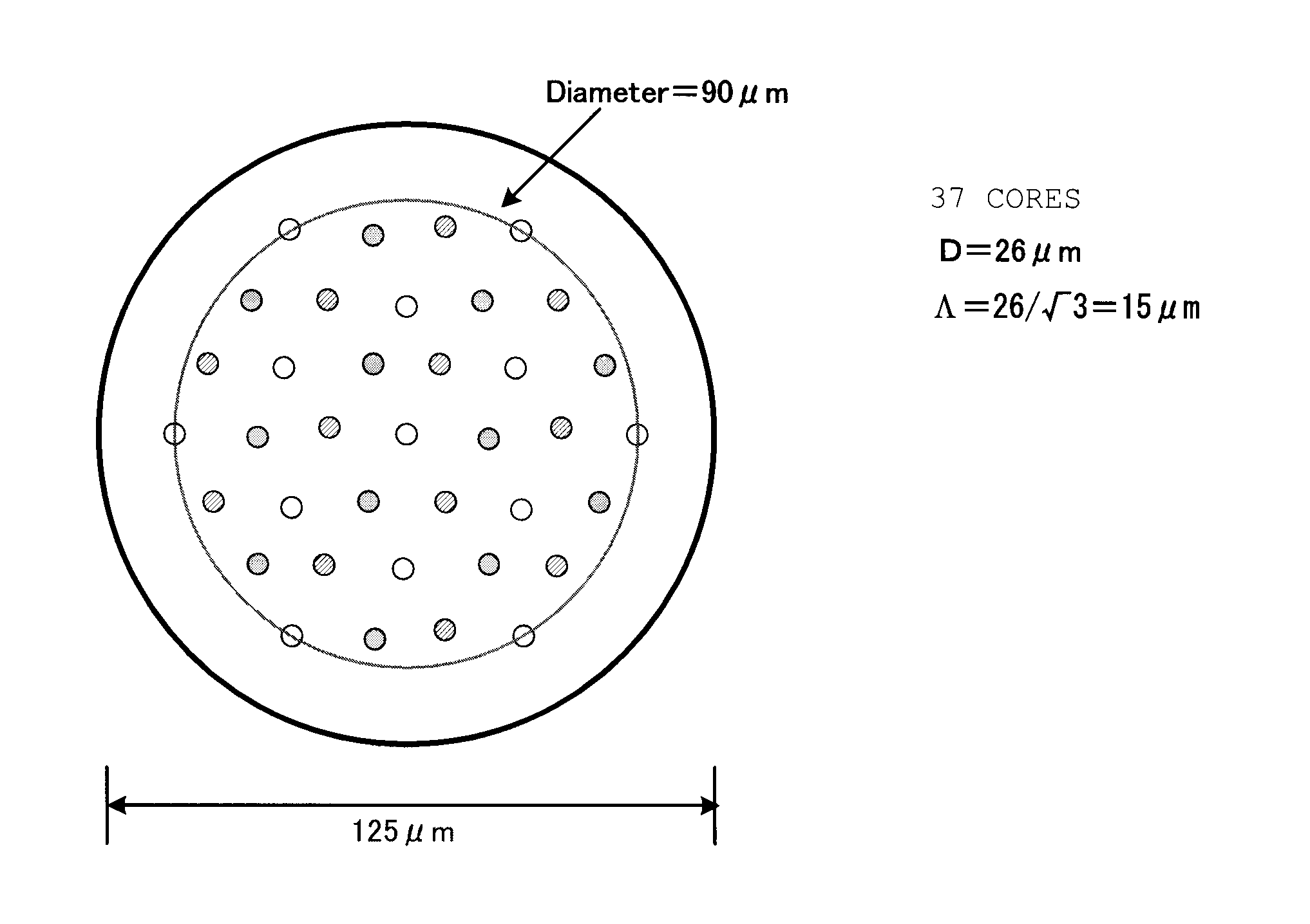
[0117]The present invention relates to a multicore fiber that uses multiple single mode cores composed of heterogeneous cores with different propagation constants and homogeneous cores with the same propagation constant or that uses multiple single mode cores composed of only the homogeneous cores with the same propagation constant. The present invention varies the propagation constants of homogeneous cores, which have the same propagation constant, via a perturbation and suppresses the coupling between the homogeneous cores by varying the propagation constants of the homogeneous cores, thus reducing the homogeneous core-to-core distance for increasing the density of the multicore fiber.

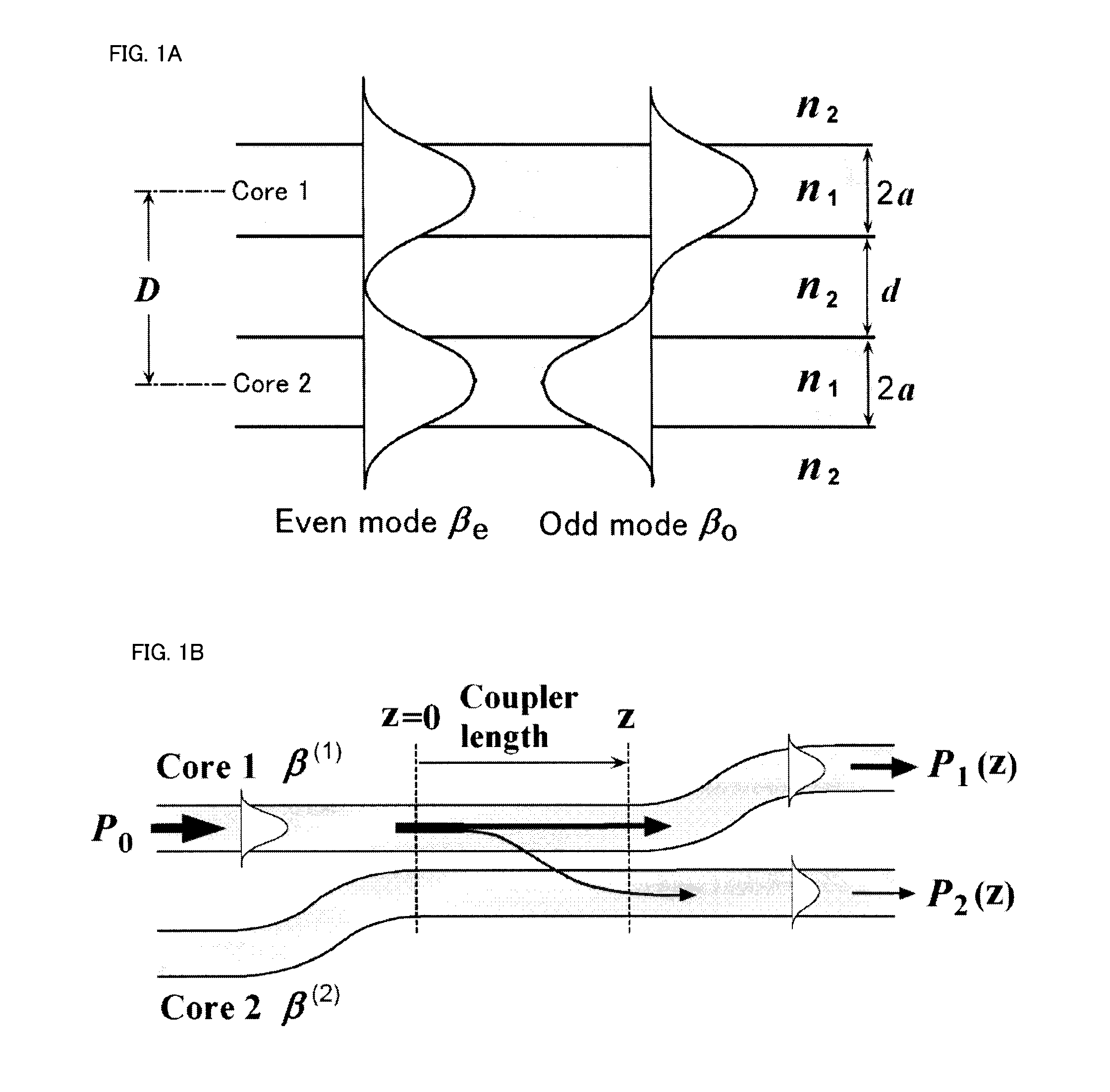
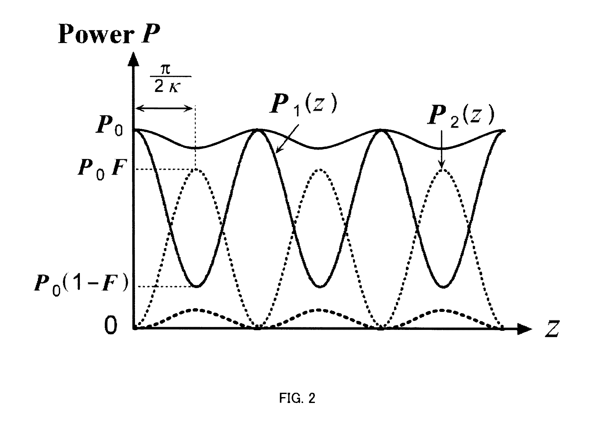
[0118]The following describes the outline of how a propagation constant is varied by a perturbation in the present invention with reference to FIGS. 1-9 and describes an example of the configur...


PUM


Abstract

In a multicore fiber in which multiple single mode cores are stored in one optical fiber, the multicore fiber has a lattice-point arrangement in which multiple lattice points are periodically arranged two-dimensionally with translational symmetry and rotational symmetry or one of translational symmetry and rotational symmetry and, in that lattice-point arrangement, multiple cores are arranged with the lattice points of the lattice-point arrangement as reference positions. By giving different perturbations to the propagation constants of the cores, the propagation constants of the cores are each varied from the original propagation constants. Because of the variation in the propagation constants, the core-to-core coupling amount, which is dependent on the varied propagation constants, fall below a predetermined setting amount. Suppressing the coupling between homogeneous cores in this way reduces the distance between the homogeneous cores, thus increasing the core density of the multicore fiber without increasing the types of heterogeneous cores.

Description

TECHNICAL FIELD[0001]The present invention relates to a multicore fiber for use in dense space-division multiplexed transmission and a core arrangement method for a multicore fiber.BACKGROUND ART[0002]As terms for representing an inter-core coupling state in a general sense, the term “coupled state” and the term “incomplete coupled state” are used. As terms for representing an inter-core coupling state in a more strict sense, the term “complete coupled state” and the term “non-coupled state” are used.[0003]The term “coupled state” represents the coupling state in which the coupling ratio is almost 1, and the term “incomplete coupled state” represents the coupling state in which the coupling ratio is smaller than 1 but not completely 0.[0004]The term “complete coupled state” represents the coupling state in which the coupling ratio is completely 1, and the term “non-coupled state” represents the coupling state in which the coupling ratio is so close to 0 that the coupling ratio canno...

Claims


Application Information

Patent Timeline
Patent Type & Authority Applications(United States)
IPC IPC(8): G02B6/02
CPCG02B6/02042G02B6/02328G02B6/02338G02B6/1225G02B6/02352G02B6/02357G02B6/02347G02B6/032
Inventor KOKUBUN, YASUOTOMOZAWA, KOHEI
Owner NAT UNIV CORP YOKOHAMA NAT UNIV
Why Eureka
Try Eureka