System and method for multiple sub-octave band transmissions

a transmission system and sub-octave technology, applied in the direction of fibre transmission, distortion/dispersion elimination, electrical equipment, etc., can solve problems such as reducing clarity

Inactive Publication Date: 2013-06-20
TIOPTICS INC
View PDF6 Cites 5 Cited by
  • Summary
  • Abstract
  • Description
  • Claims
  • Application Information

AI Technical Summary

Benefits of technology

[0007]In accordance with the present invention, a Passive Optical Network (PON) incorporates a band pass filter for removing second order distortions from an optical signal that are induced when a light beam is transmitted through a fiber optic cable in the PON. In accordance with the present invention, the optical signal from the fiber optic cable is converted to an RF signal, and the RF signal is filtered in the sub-octave bandwidth that includes the RF carrier frequency of the digital signal. The RF signal can then be demodulated for subsequent reception of the digital signal.
[0016]For this aspect of the present invention, the second sub-octave band is spaced from the first sub-octave band by a non-transmission band (i.e. a non-transmission band between F2 and F3). Moreover, to reduce second order distortions, the non-transmission band is established with F3>2F2. Additional bands can be employed above the second band or below the first band. The bandwidth of the additional bands and non-transmission bands between bands can be calculated using the techniques provided herein to reduce or eliminate the effects of second order distortions. Typically, frequencies in the bands described above are in a range of frequencies between 750 MHz and 40 GHz.

Problems solved by technology

A potential downside, however, is that fiber optic cables are known to introduce distortions into an optical signal that diminish its clarity.

Method used


Image

  • System and method for multiple sub-octave band transmissions
  • System and method for multiple sub-octave band transmissions
  • System and method for multiple sub-octave band transmissions

Examples


Embodiment Construction

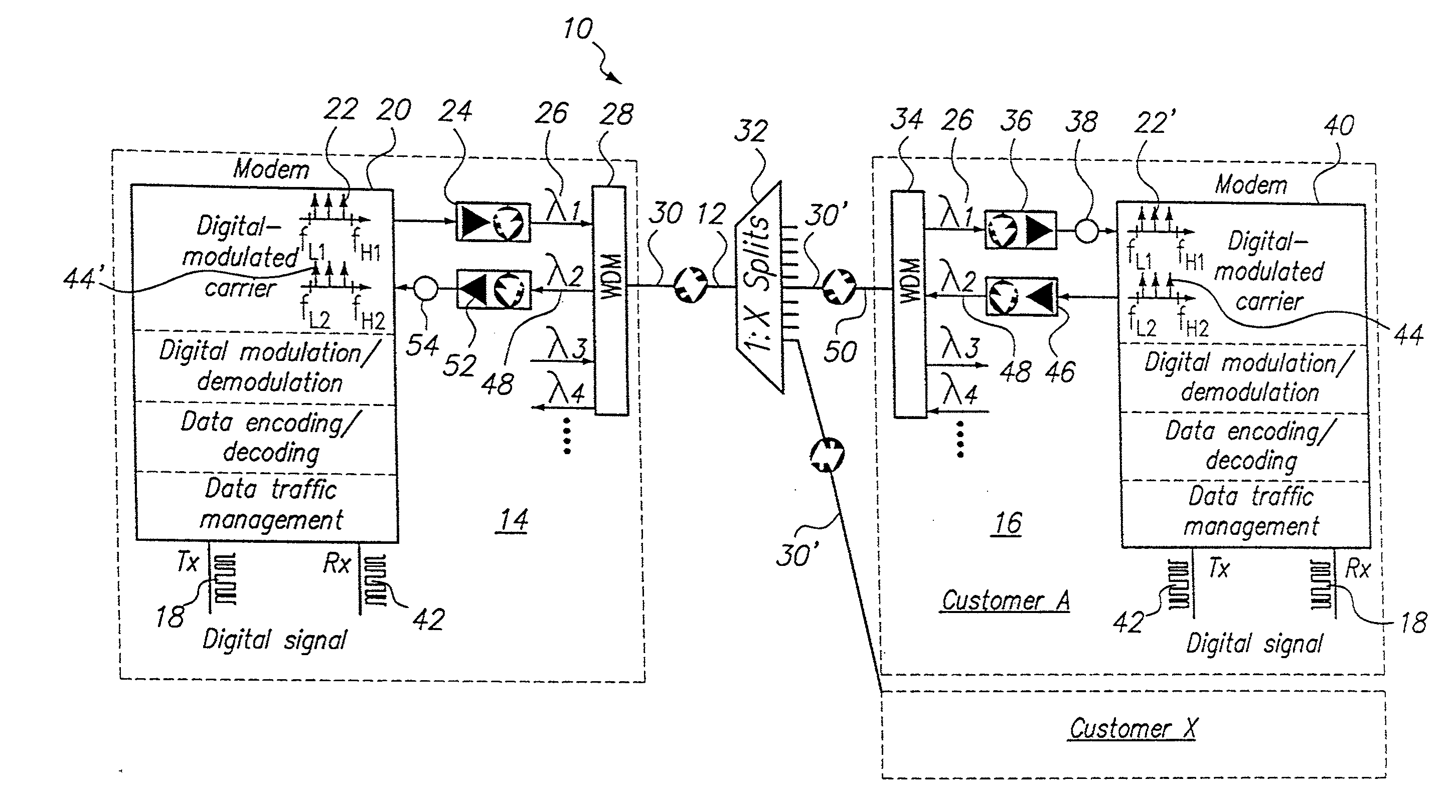
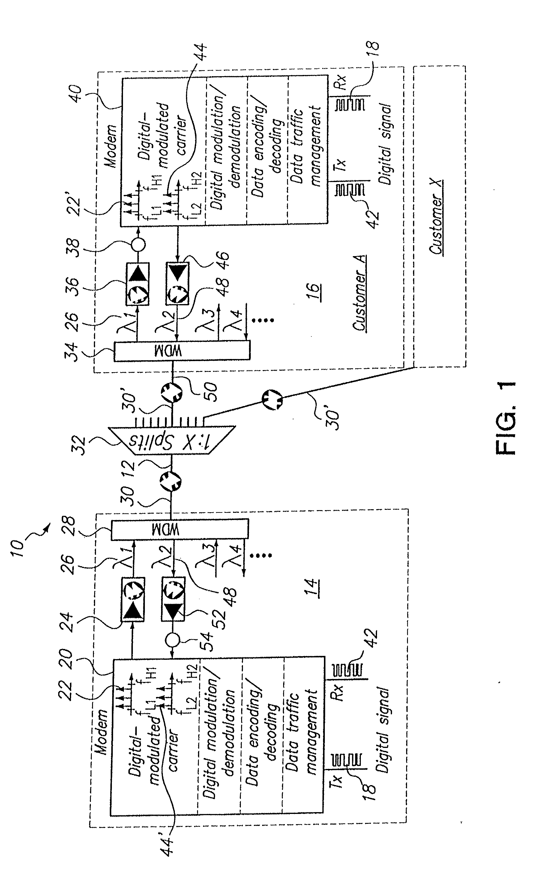
[0024]Referring initially to FIG. 1, component elements of a Passive Optical Network (PON) in accordance with the present invention are shown collectively and generally designated 10. As shown, the PON 10 includes a fiber optic cable (optical fiber) 12 that interconnects an Optical Line Terminal (OLT) 14 (e.g. a service provider) with a plurality of Optical Network Units (ONU) 16 (e.g. customers). In FIG. 1, the ONU 16 is only exemplary, and is shown to be servicing Customer A.

[0025]As indicated in FIG. 1, a digital signal 18 that is to be transmitted over the PON 10 is modulated by the modem 20. For purposes of the PON 10, this modulation may be either an amplitude modulation, a frequency modulation, phase modulation, or any combination of the three. In any event, the digital signal 18 is modulated onto an RF carrier frequency (f1) in a manner well known in the pertinent art. In FIG. 1, it is shown that the modulated carrier frequency 22 (i.e. f1) is established in a sub-octave tha...


PUM


Abstract

A system and method for enabling multiple sub-octave band transmissions with reduced second order distortions is provided. For this method, first and second sub-octave bands are established. The second sub-octave band is spaced from the first sub-octave band by a non-transmission band. Digital signals are modulated onto RF carrier frequencies in the first and second band to produce first band RF signals and second band RF signals. The first and second band signals are converted into one or more light beams and transmitted over a fiber optic cable. After transmission, an optical receiver reconverts the light beam into an RF signal. Second order distortions outside a selected sub-octave band can be filtered from RF signal and a tuner used to tune in a selected carrier frequency. A receive modem can then be used to demodulate the tuned carrier frequency for receipt of its respective digital signal.

Description

[0001]This application is a continuation-in-part application of U.S. patent Ser. No. 12 / 980,008, filed Dec. 28, 2010 to inventor Chen-Kuo Sun, (attorney docket number 11576.2) the entire contents of which are hereby incorporated by reference herein.FIELD OF THE INVENTION[0002]The present invention pertains generally to systems and methods that enable transmissions of data over optical fibers. More particularly, the present invention pertains to systems and methods for transmitting digital signals over fiber optic networks with subsequent sub-octave filtering to remove second order distortions from the signals. The present invention is particularly, but not exclusively, useful as a system and method for using a Passive Optical Network (PON) to transmit digital signals with subsequent sub-octave filtering.BACKGROUND OF THE INVENTION[0003]A Passive Optical Network (PON) is essentially an optical network that uses a single fiber optic cable for the transmission of signals from one point...

Claims


Application Information

Patent Timeline
Patent Type & Authority Applications(United States)
IPC IPC(8): H04B10/2507
CPCH04B10/2507H04B10/2543H04J14/0298H04J14/0282H04B10/25754
Inventor SUN, CHEN-KUOWOLFF, PETER H.
Owner TIOPTICS INC
Why Eureka
Try Eureka