Method and device for transmission and reception in a multi-input and multi-output channel distributing a code word between several mapping matrices, and corresponding computer program

a multi-input and multi-output technology, applied in the field of digital communication, can solve the problems of 3 db loss of performance as compared with transmission, non-coherent mimo differential techniques, and lack of encoding gain, so as to reduce the need for channel knowledge and improve the effect of building efficiency

Active Publication Date: 2013-06-20
ORANGE SA (FR)
View PDF1 Cites 14 Cited by
  • Summary
  • Abstract
  • Description
  • Claims
  • Application Information

AI Technical Summary

Benefits of technology

[0064]Thus, an embodiment of the invention relies on a novel and inventive approach to the reception and decoding of data sent in a channel having undergone processing at sending as described here above with reference to the method for sending according to an embodiment of the invention, enabling the code sent to be rebuilt more efficiently than in the prior art, while at the same time removing the need for knowledge of the channel.
[0065]Indeed, since the two matrices sent according to the method for sending being chosen to be invertible and complying with the criterion of uniqueness of the cancellation of the syndrome associated with the code word c, the method for receiving according to an embodiment of the invention includes finding the unique pair of decoding matrices (Ma,Mb) minimizing the norm of the syndrome associated with the code word c, from among the set of possible pairs (Ma,Mb) corresponding to the possible code words c sent.
[0066]Since the matrices Mα and Mβ sent result from the redundant encoding according to the error-correcting code chosen when sending and from the mapping in a set of invertible matrices, the search for minimizing the syndrome associated with the code word c is implemented on all the possible code words c and therefore on all the possible source words x which have (Ma, Mb)(x) as their images. An embodiment of the invention thus enables the rebuilding of the source word x.

Problems solved by technology

These non-coherent MIMO differential techniques however do not implement any error correcting and therefore do not have any encoding gain.
A first drawback of these techniques lies in a 3 dB loss of performance as compared with transmissions made with knowledge of the propagation channel, at least in part because of the absence of encoding gain due to the absence of error-correcting encoding.
The performance is then improved but the 3 dB loss at the differential detection level cannot be compensated for.
However, the main drawback of these differential techniques lies in the need to assume that the channel is constant during a long block of data elements to be transmitted, which is the basic assumption of these techniques.
This assumption is indeed highly constraining and unrealistic, especially for the radio-electrical channels used in practice for transmissions to and from the mobile terminals.

Method used


Image

  • Method and device for transmission and reception in a multi-input and multi-output channel distributing a code word between several mapping matrices, and corresponding computer program
  • Method and device for transmission and reception in a multi-input and multi-output channel distributing a code word between several mapping matrices, and corresponding computer program
  • Method and device for transmission and reception in a multi-input and multi-output channel distributing a code word between several mapping matrices, and corresponding computer program

Examples


second embodiment

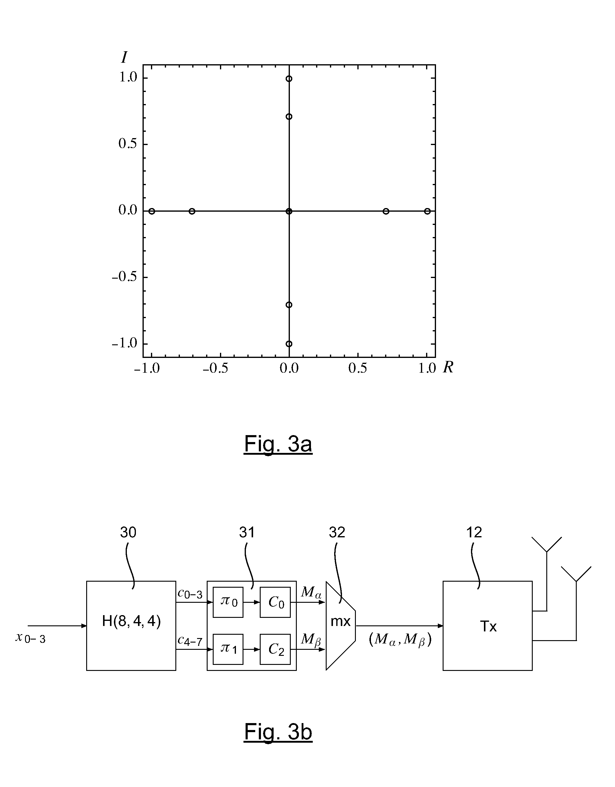
[0138]3. Description of a Second Embodiment Referring to FIGS. 4, 5a and 5b, a description is now given of a second example of an embodiment of the invention implementing a 2×2 matrix modulation and a convolutive error-correcting code deduced from the (8,4,4) Hamming block code in unfolding and repeating its 4-state tail-biting trellis to infinity, for a MIMO system comprising two sending antennas and two receiving antennas.

[0139]This convolutive code known as a Hamming code is built from the trellis known as the “tail-biting” trellis or circular trellis of the Hamming block code described here above.

[0140]This small convolutive code, the trellis of which is very simple, as shown in FIG. 5a for a 4-state trellis with three sections, enables the principle of this embodiment to then be extended to all the codes capable of including one or more trellises in their description such as for example the turbo-codes described especially in the document by Claude Berrou and al., “Codes and tu...

third embodiment

[0161]4. Description of a Third Embodiment

[0162]Referring to FIGS. 6a to 6c, a description is now given of a third example of an embodiment of the invention implementing a 2×2 matrix modulation and a Golay convolutive error-correcting code for a MIMO system comprising two sending antennas and two receiving antennas.

[0163]According to this embodiment, the mapping matrices are no longer selected in the Weyl group but built so as to comply with the properties required by an embodiment of the invention, namely invertibility and compliance with the criterion of uniqueness of the cancellation of the syndrome.

[0164]Thus, as illustrated in FIG. 6a from a sliding window of four bits x03=(x0, x1, x2, x3) of information to be transmitted, the step 60 of convolutive encoding produces eight bits c07=(c0, C1, c2, . . . c7).

[0165]The code used is for example the convolutive Golay code described in E. Cadic, J. C. Carlach, G. Olocco, A. Otmani and J. P. Tillich, “Low Complexity Tail-Biting Trellise...

fourth embodiment

[0183]5. Description of a Fourth Embodiment

[0184]As already indicated here above, in a fourth embodiment, the invention enables the transmission of 16 encoded bits c0-15.

[0185]To this end, an embodiment of the invention uses a modulation close to the MAQ16 modulation where the first level is mapped towards (±1±as for the previous embodiment and the second level towards (±1±) / 2.

[0186]According to this embodiment of the invention, the eight first bits are mapped so as to obtain a first invertible matrix A=M(c0-7) and the last eight bits c8-15 are mapped so as to obtain a second invertible matrix B=M (c8-15) .

[0187]The overall mapping matrix obtained corresponds to the sum (A+B / 2) which is an invertible matrix with complex coefficients, the constellation of which is shown in FIG. 7a.

[0188]The other steps when sending and then receiving are identical to the third embodiment described here above.


PUM


Abstract

A method for transmitting a source binary sequence, including at least one source word, in a transmission channel, The method includes the following steps, for at least one source word: error-correcting encoding the source word, outputting a code word; matrix mapping the code word, distributing bits constituting the code word within at least two mapping matrices, which are reversible and observe a criterion of uniqueness in the cancellation of a syndrome associated with the code word; and consecutively transmitting the at least two mapping matrices.

Description

CROSS-REFERENCE TO RELATED APPLICATIONS[0001]This Application is a Section 371 National Stage Application of International Application No. PCT / FR2011 / 051977, filed Aug. 29, 2011, which is incorporated by reference in its entirety and published as WO 2012 / 042140 on Apr. 5, 2012, not in English.STATEMENT REGARDING FEDERALLY SPONSORED RESEARCH OR DEVELOPMENT[0002]None.THE NAMES OF PARTIES TO A JOINT RESEARCH AGREEMENT[0003]None.FIELD OF THE DISCLOSURE[0004]The field of the disclosure is that of digital communications.[0005]More specifically, the disclosure pertains to the transmission of data by radio-electrical communications or radio communications and more particularly radio transmission systems with several sending antennas and several receiving antennas known as MIMO or multi-input multi-output radio transmission systems.[0006]The disclosure can be applied especially in digital radio networks such as GSM or UMTS systems or WiFi radio networks as well as future communications syste...

Claims


Application Information

Patent Timeline
Patent Type & Authority Applications(United States)
IPC IPC(8): H03M13/05
CPCH04B7/0413H04L1/0057H04L1/06H03M13/05H04L25/497H04L2025/03426H04L25/03343
Inventor CARLACH, JEAN-CLAUDEEL ARAB, ALIHELARD, MARYLINE
Owner ORANGE SA (FR)
Why Eureka
Try Eureka