Thermal imager with protective grid

a technology of thermal imager and protective grid, which is applied in the direction of optical radiation measurement, radiation control device, electrical apparatus casing/cabinet/drawer, etc., can solve the problem of non-radiometric thermal measurement of thermal imager

Active Publication Date: 2013-06-27
JOHN FLUKE MFG CO INC
View PDF3 Cites 8 Cited by
  • Summary
  • Abstract
  • Description
  • Claims
  • Application Information

AI Technical Summary

Problems solved by technology

As a result, the protective grid causes a strong, non-uniform attenuation pattern in

Method used


Image

  • Thermal imager with protective grid
  • Thermal imager with protective grid
  • Thermal imager with protective grid

Examples


Embodiment Construction

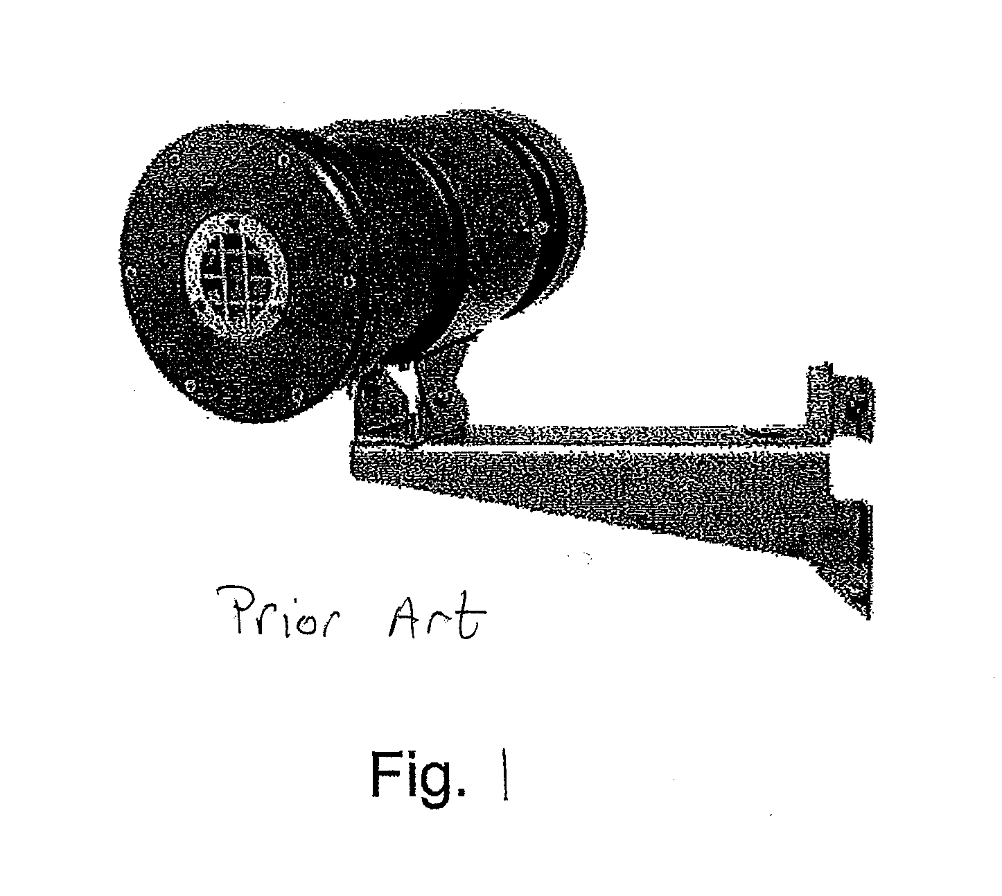
[0018]FIG. 1 is a commercially available prior art enclosure for a thermal imager. The enclosure is to be used in hazardous environments where the forming of potentially explosive atmosphere is possible due to the presence of explosive gases, smoke, and powder. These explosion proof enclosures must withstand a stringent test of impact and pressure in which it is subjected to both impact by a metal object along with a consecutive surge of internal pressure, such as IEC 60079-0 and IEC 60079-1. When the enclosure houses a thermal imager, there must be a viewport that is transparent to infrared light of long wavelengths in order for the thermal imager to be able to operate. Choice of window materials that satisfy this requirement are very limited, and, moreover, none of them offer sufficient mechanical strength to pass the impact portion of the stringent test. The most common material used for the window is germanium (Ge) which with sufficient thickness, is capable of withstanding the ...


PUM


Abstract

A protective enclosure for a thermal imager having a window and protective grid. The protective grid is designed in relation to the lens of the thermal imaging device such that the grid pattern geometry and size accommodate the thermal imaging device's pupil size.

Description

BACKGROUND OF THE INVENTION[0001]Industrial monitoring systems often employ thermal, or infrared (IR), imaging devices, which are preferably mounted in a fixed location to capture IR images of a target, which may be a particular portion of a piece of manufacturing equipment and / or a product in the midst of a manufacturing process. These devices are typically adapted to communicate with a remote monitoring station and, in some instances, are integrated with a process control package.[0002]In harsh industrial environments it is often necessary to contain these imaging devices within a protective enclosure that keeps the imaging device cool and free of contaminations such as dust particles. The enclosure necessarily includes a window through which the thermal imaging device can view the target in the environment over a period of time.[0003]In an explosion-proof housing, a protection grid must be used to protect the window from the external environment. The protective grid is typically ...

Claims


Application Information

Patent Timeline
IPC IPC(8): H01L27/146G06F17/50H05K5/00
CPCG01J5/0875G01J5/048
Inventor NIKITTIN, ALEX S.ALVAREZ, JR., SALVADOR
Owner JOHN FLUKE MFG CO INC
Why Eureka
Try Eureka