Method for determining a voltage bounding range

a voltage bounding range and voltage technology, applied in the direction of electric generator control, machines/engines, mechanical apparatus, etc., can solve the problems of unsatisfactory behaviour and inability to achieve satisfactory performance of wind turbines, and achieve the effect of avoiding or reducing damage to components of wind turbines and improving the determination of voltage bounding rang

Active Publication Date: 2013-06-27
SIEMENS GAMESA RENEWABLE ENERGY AS
View PDF10 Cites 9 Cited by
  • Summary
  • Abstract
  • Description
  • Claims
  • Application Information

AI Technical Summary

Benefits of technology

[0041]Restricting the voltage bounding range between the absolute maximum voltage and the absolute minimum voltage may be necessary in order to avoid damage of components of the wind turbine. In particular, the wind turbine may be defined to be operated at voltages between the absolute maximum voltage and the absolute minimum voltage. Thereby, damages of components of the wind turbine may be avoided or reduced.
[0042]According to one embodiment, the method further comprises measuring the characteristic of the transmission line, in particular regarding possible voltages at the transmission line. In particular, the voltage and / or active power and / or reactive power and / current may be measured at the point of common coupling. In particular, the voltage and / or active power and / or reactive power and / or current may be measured at the wind turbine output terminal. Further, such electrical quantities may be measured at plural different locations along the transmission line between the wind turbine and the point of common coupling. Thereby, the determination of the voltage bounding range may further be improved.

Problems solved by technology

However, it has been observed, that in some situations applying a fix range does not lead to satisfactory performance of the wind turbines, in particular in the case of changing grid characteristics.
Further, it has been observed that a wind turbine voltage controller may be saturated in particular conditions leading to unsatisfactory behaviour.

Method used


Image

  • Method for determining a voltage bounding range
  • Method for determining a voltage bounding range
  • Method for determining a voltage bounding range

Examples


Embodiment Construction

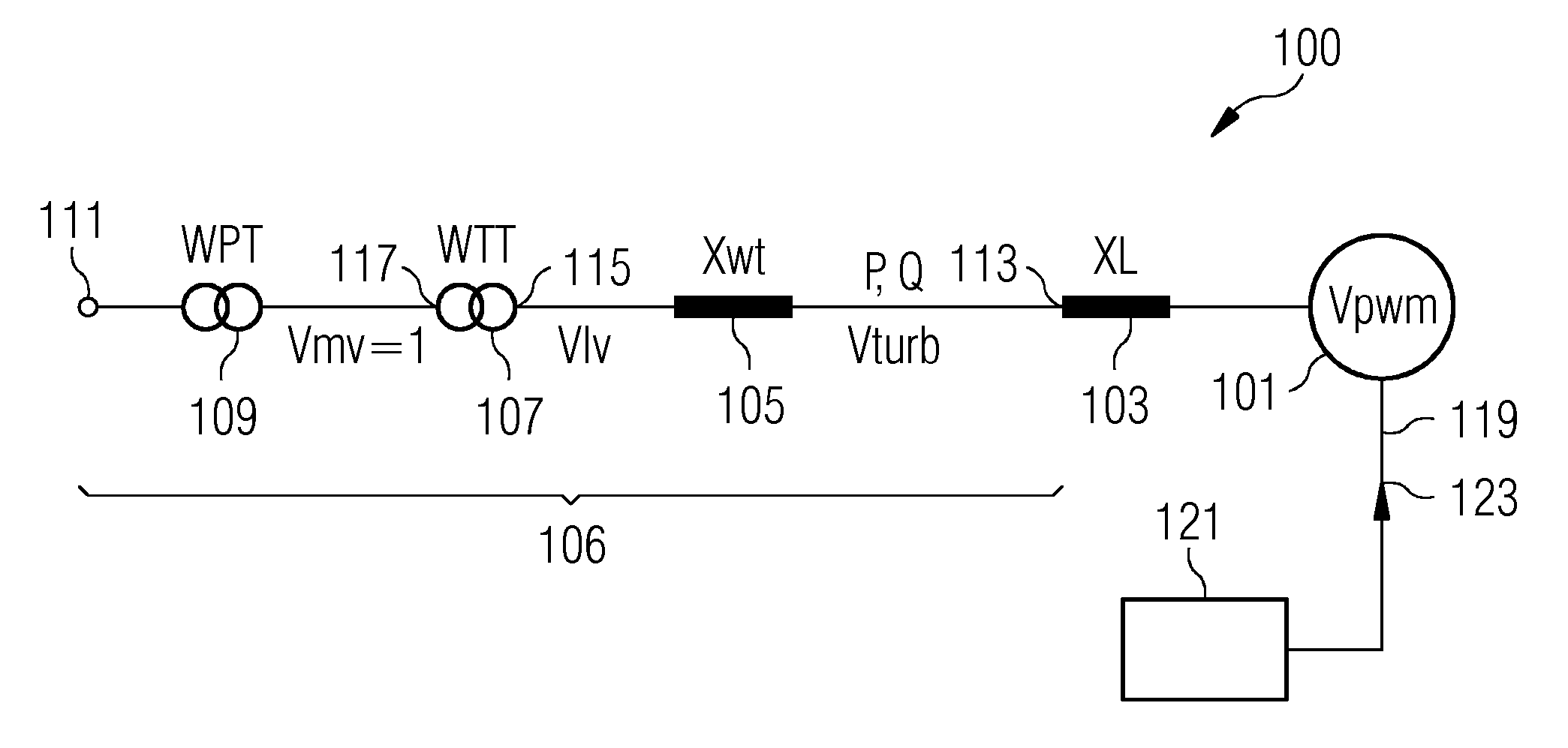
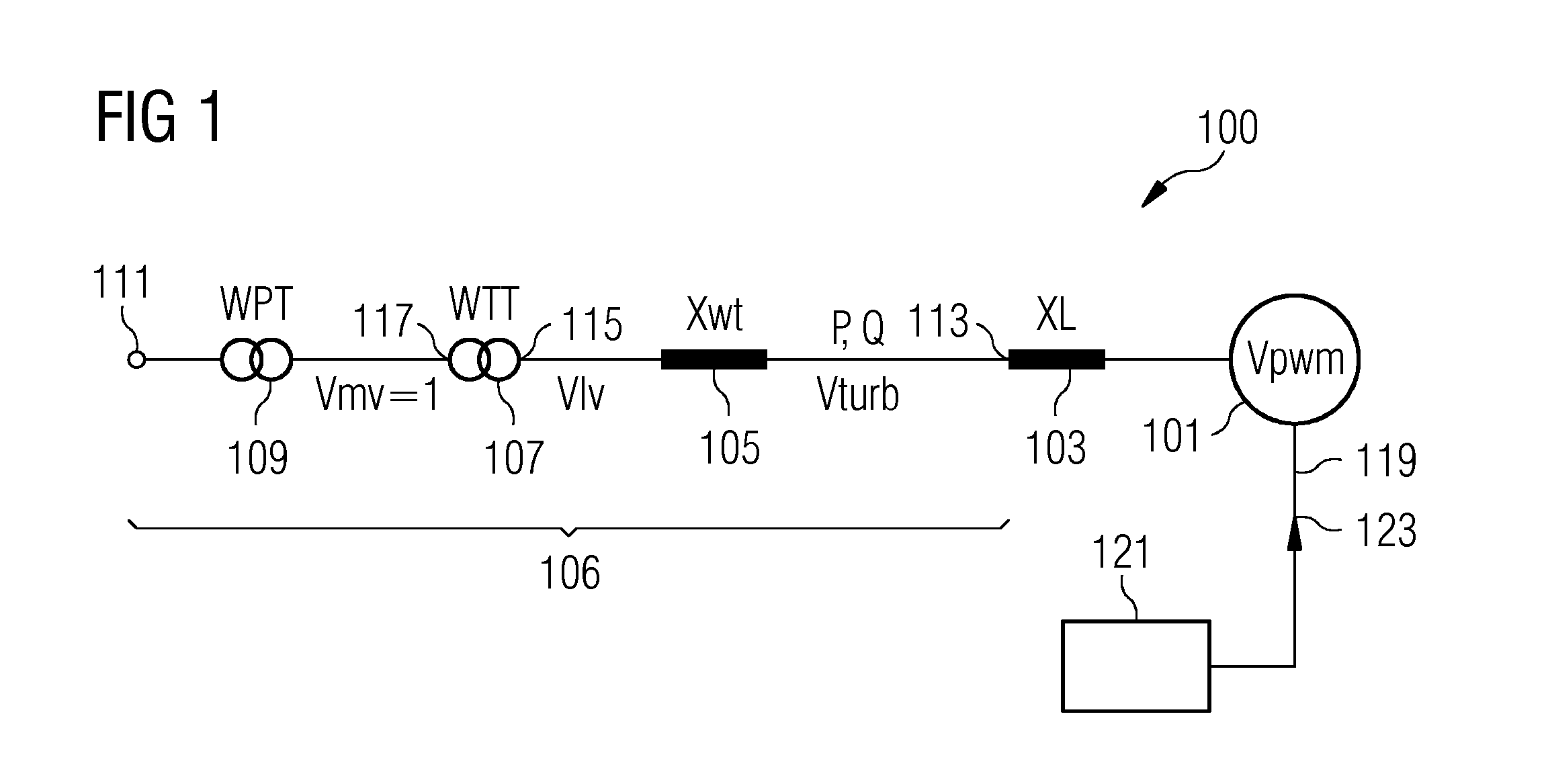
[0057]FIG. 1 schematically illustrates a portion 100 of a wind farm, wherein a wind turbine 101 is connected via an inductor or reactor 103 (XL), an inductor 105 (XWT), a wind turbine ideal transformer 107 (the inductor 105 represents the short circuit / leakage inductance of the transformer 107) (WTT) and a wind park transformer 109 (WTT) to a point of common coupling 111 to which not illustrated other wind turbines may be connected.

[0058]At an output terminal 113 the wind turbine 101 generates (filtered by reactor 103 filtering out high frequency components) the output voltage Vturb comprising active power P and reactive power Q. At the low voltage side 115 of the wind turbine transformer 107 a voltage Vlv is present and on a medium voltage side 117 of the wind turbine transformer 107 a voltage Vmv is present, wherein Vmv is typically constant but may occasionally change depending on grid condition.

[0059]The wind turbine transformer 107 is a tap transformer providing a variable tran...


PUM


Abstract

A method is provided for determining a voltage bounding range defining a range of a wind turbine reference voltage for a wind turbine for controlling an output voltage of the wind turbine at a wind turbine output terminal The method includes obtaining information regarding an electrical characteristic of a transmission line connecting the wind turbine output terminal to a point of common coupling to which plural other wind turbines are connectable. The method further includes defining the voltage bounding range based on the electrical characteristic of the transmission line.

Description

CROSS REFERENCE TO RELATED APPLICATIONS[0001]This application claims priority of European Patent Office application No. 11195355.0 EP filed Dec. 22, 2011. All of the applications are incorporated by reference herein in their entirety.FIELD OF INVENTION[0002]The illustrated embodiments relate to a method for determining a voltage bounding range defining a range of a wind turbine reference voltage for a wind turbine for controlling an output voltage of the wind turbine, to a method and to an arrangement for determining a wind turbine reference voltage using the method for determining the voltage bounding range.BACKGROUND OF INVENTION[0003]A wind turbine part may comprise plural wind turbines which may be electrically connected to a common coupling point (PCC) and which wind turbines may be controlled by a park controller or park pilot. The park pilot may send a voltage reference to each of the wind turbines.[0004]Thereby, in a conventional wind turbine park the voltage reference is li...

Claims


Application Information

Patent Timeline
Patent Type & Authority Applications(United States)
IPC IPC(8): H02P9/04
CPCF03D9/005Y02E10/723F03D7/0284Y02E40/34H02J3/386Y02E10/763H02J3/16F03D9/257H02J2300/28H02J3/381Y02E10/76Y02E10/72Y02E40/30
Inventor BECH, JOHNBO, YIN
Owner SIEMENS GAMESA RENEWABLE ENERGY AS
Why Eureka
Try Eureka