Thermal cutoff link safety fuse in HVAC system

a safety fuse and cutoff link technology, applied in the direction of thermally actuated switches, electric switches, electrical apparatus, etc., can solve the problems of failure of devices to open, failure of traditional electrical devices employed in hvac systems to fail in “closed” mode, and the majority of overheating protection devices used in hvac systems are not fail-safe mechanisms, so as to prevent the continued heating of airflow, reduce or eliminate the risk of fire, and the effect of preventing the continued heating o

Inactive Publication Date: 2013-06-27
KELLEY ROY
View PDF5 Cites 5 Cited by
  • Summary
  • Abstract
  • Description
  • Claims
  • Application Information

AI Technical Summary

Benefits of technology

[0018]The thermal cut off link safety fuse is installed by electrically connecting its two open terminals in series with the heater coil circuit of the HVAC system and placing it within the airflow where heat detection and cutoff is desired. As the airflow heats up and exceeds the temperature rating of the device, the fuse element in the device melts and the current flow to the heater coil is interrupted, this preventing the continued heating of airflow and reducing or eliminating the risk of fire.
[0019]It is therefore an object of the present invention to provide for an HVAC temperature protection device which is simple, reliable, and fail-safe and which relies on direct temperature sensing rather than indirect measurements such as over-current or over-voltage situations.
[0020]It is a further object of the present invention to provide a system that can protect from failure due to heat from fire and heat created when the air flow is blocked.
[0021]It is a further object of the present invention to provide a fail-safe thermal fuse that is lower in cost than other non-fail-safe devices currently utilized.
[0022]It is a further object of the present invention to provide a fail-safe device that can be easily and readily removed and replaced without the need to remove the heater assembly from the HVAC ductwork or HVAC system.

Problems solved by technology

Most of the overheat protection devices used in the HVAC systems are not fail-safe mechanisms.
Over periods of time, traditional electrical devices employed in HVAC systems may fail in the “closed” mode.
This may be caused by melting and welding of contact points or by mechanical failure.
In such a failure mode, the devices will fail to open when an over-voltage or over-current condition is present and expose other components to dangerous electrical loads.
This could lead to damage to electrical components and / or excessive temperatures which could, in turn, lead to catastrophic fires.
One of the most common causes of failure in traditional electrical overload devices is overvoltage.
Overvoltage is considered a safety hazard by all industry standards, and can cause premature failure of connected equipment.
Instances of severe cold weather during the heating seasons can cause power company protection devices to trip off power (serving a number of distribution zones) due to overloads.
The sudden load losses can cause voltage to suddenly increase above the limit at points of use in the distribution systems that remain on-line.
Overvoltage can cause damage to electrical equipment of all types, including HVAC equipment, circuit boards, relays, and reversing valves.
Any of this damage can result in a fire.
Most traditional, thermal over-temperature devices are not fail-safe because they can fail to open the electrical circuit to the heating element(s), and allow unchecked over-heating to surrounding materials which over-heat and cause fire.
These devices are not considered fail-safe and can fail in the closed position, with the contacts welded together.
This can occur due to excessive on-off cycling of the device when the incoming utility voltage exceeds the legal limits and / or when the indoor system airflow is less than the minimum requirements.
These conditions usually go unnoticed by occupants, uncorrected by technicians and may develop over years leading to an inevitable catastrophic failure and likely a fire.
Low airflow causes auxiliary electric heaters to short-cycle by their auto-reset primary high temperature safety limits and become inoperative by their secondary back-up safety limits.
It is also widely known that low airflow will cause heat pump compressors to short-cycle by their auto-reset high head pressure limits.
Both the electric heater and the compressor are subject to premature failure depending on the degree of low airflow and the length of time in use.
However, there is a possibility that such temperature control unit operates abnormally due to a failure in the logic or the electronic components of its internal control circuit.
As summarized above, the biggest disadvantage in the existing HVAC overheat protection technology is that it either relies on detecting elevated current or voltage levels in the circuits powering the system or, if it detects elevated temperatures, it is not fail-safe.
Under such conditions, excess heat could accumulate in vents and ducts and because no excess current or voltage is detected, the system would continue to generate heated air making the risk of fire even greater.
Existing overheat protection technology which relies in direct temperature measurements, e.g., automatic reset temperature limiters and electronic temperature control units, is disadvantageous in that they are complicated and prone to failure because of the multiple parts required to operate them.
Moreover, these technologies are not fail-safe and can therefore fail without providing warning to the user, leaving the HVAC system open to catastrophic fire damage.
Another big disadvantage of current systems is the failure of over-temperature or overheat protection devices in a HVAC system when the air flow is restricted or blocked.

Method used


Image

  • Thermal cutoff link safety fuse in HVAC system
  • Thermal cutoff link safety fuse in HVAC system
  • Thermal cutoff link safety fuse in HVAC system

Examples


Embodiment Construction

[0028]While the present invention will be described more fully hereinafter with reference to the accompanying drawings, in which one or more embodiments of the present invention is shown, it is to be understood at the outset of the description which follows that persons of skill in the appropriate arts may modify the invention herein described while still achieving the favorable results of this invention. Accordingly, the description which follows is to be understood as being a broad, teaching disclosure directed to persons of skill in the appropriate arts, and not as limiting upon the present invention.

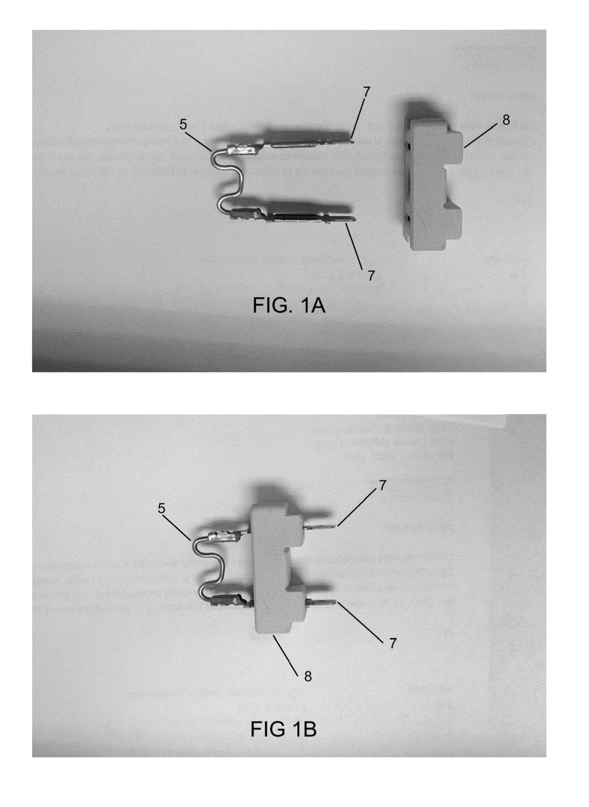
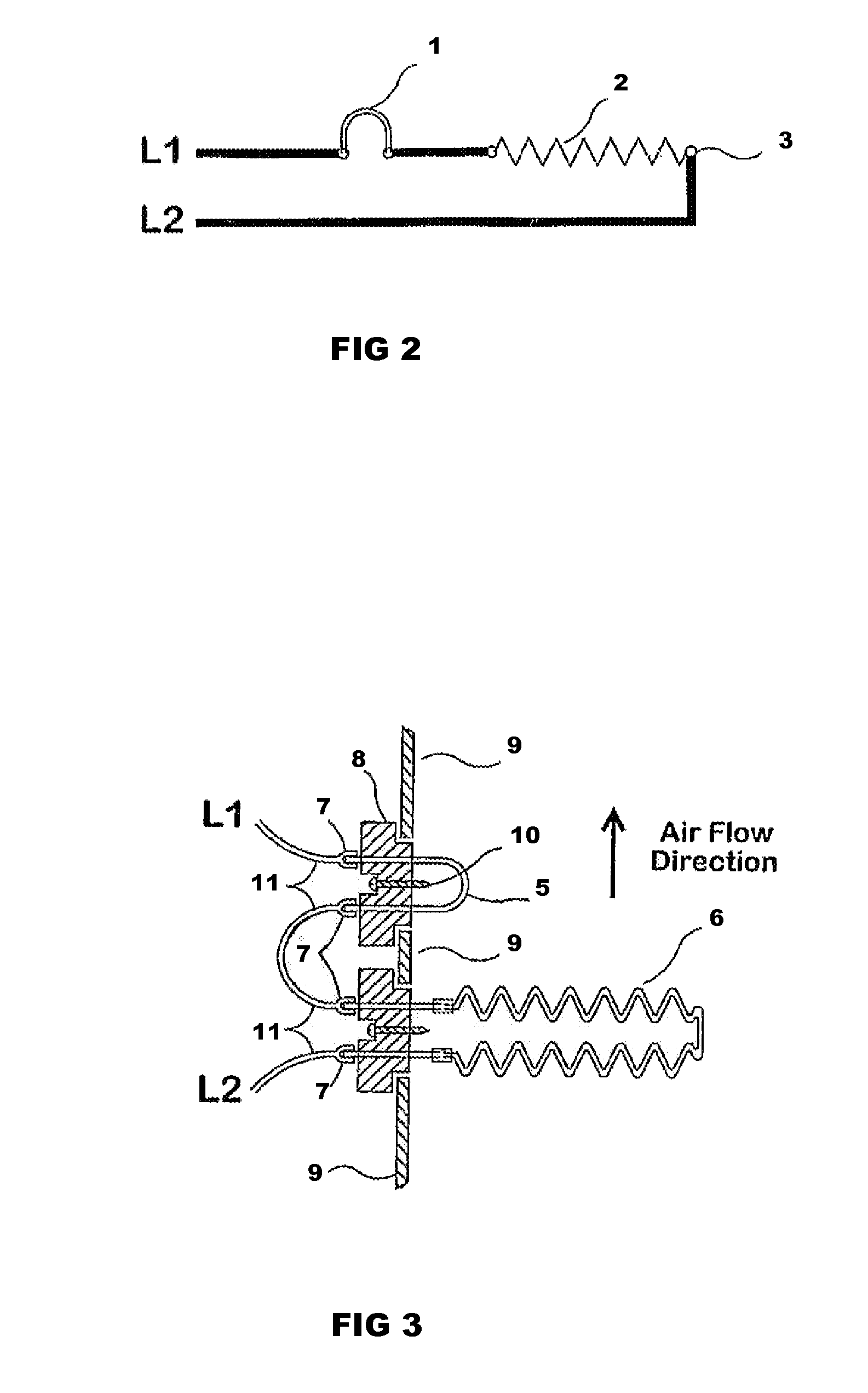
[0029]The current invention satisfies the needs in the industry by providing a thermal cut off link safety fuse for use in HVAC systems. The thermal cut off link safety fuse is comprised of a terminal block, two double-sided electrical terminals mounted on the terminal block, and a length of conductive heat-sensitive fuse element which is electrically connected to one side of each of...


PUM


Abstract

The present invention relates to a thermal cut off link safety fuse for use in a HVAC system. The thermal cut off link safety fuse disconnects the electrical circuit from the HVAC system's heating element when the thermal cut off link safety fuse melts upon reaching a temperature that exceeds a set temperature. The use of the thermal cut off link safety fuse in a HVAC system helps prevent fires caused by blocked airflow, insufficient airflow or excessive heat within the HVAC system

Description

TECHNICAL FIELD[0001]The present invention relates to a thermal cut off link safety fuse for use in a HVAC system. The thermal cut off link safety fuse disconnects the electrical circuit from the HVAC system's heating element when the thermal cut off link safety fuse melts upon reaching a temperature that exceeds a set temperature. The use of the thermal cut off link safety fuse in a HVAC system helps prevent fires caused by blocked airflow, insufficient airflow or excessive heat within the HVAC system.BACKGROUND OF THE INVENTION[0002]Currently, the over-temperature or overheat protection devices used in HVAC systems are the same over-temperature protection devices commonly used in electric heaters. As used herein, the term “HVAC systems” includes heating, ventilation, air conditioning systems and related duct work. Most of the overheat protection devices used in the HVAC systems are not fail-safe mechanisms.[0003]In general, electrical systems often include components such as circu...

Claims


Application Information

Patent Timeline
Patent Type & Authority Applications(United States)
IPC IPC(8): H01H85/00
CPCH01H37/761H01H37/002
Inventor KELLEY, ROY
Owner KELLEY ROY
Why Eureka
Try Eureka