Dual-polarized optically controlled microwave antenna

Active Publication Date: 2013-06-27
SONY CORP
View PDF4 Cites 240 Cited by
  • Summary
  • Abstract
  • Description
  • Claims
  • Application Information

AI Technical Summary

Benefits of technology

[0010]It is an object of the present invention to provide an optically controlled microwave antenna having a lower power consumption compared to known optically controlled microwave antennas and providing t

Problems solved by technology

In particular PIN diode based switches suffer from a high power consumption, high losses and can hardly be integrated into a microwave antenna operating above 100 GHz.
MEMS switches require high control voltages and have very slow switching speed.
FET-based switches suffer from high insertion losses and require a large biasing network.
Ferroelectric phase shifters allow rapid

Method used


Image

  • Dual-polarized optically controlled microwave antenna
  • Dual-polarized optically controlled microwave antenna
  • Dual-polarized optically controlled microwave antenna

Examples


Example

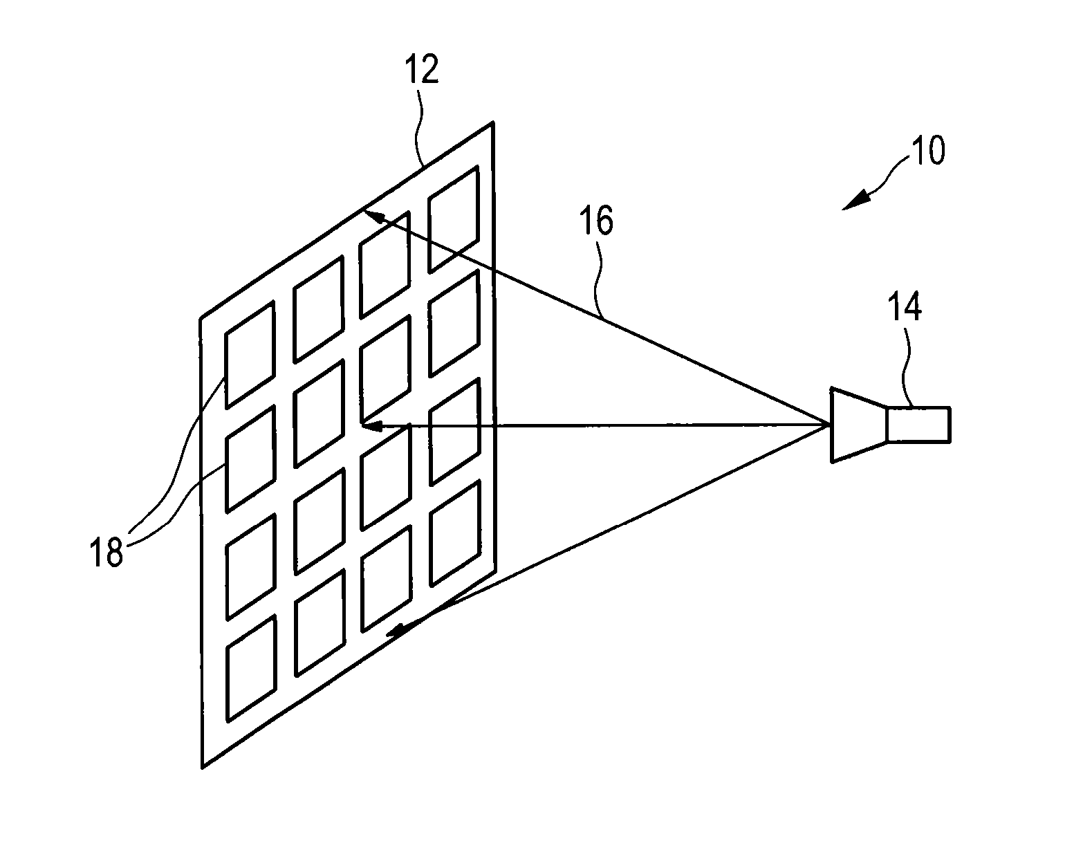
[0058]Referring now to the drawings, wherein like reference numerals designate identical or corresponding parts throughout the several views, FIG. 1 shows a general embodiment of an optically controlled microwave antenna 10 according to the present invention. The antenna 10 comprises an antenna array 12 and a feed 14 for illuminating said antenna array with and / or receiving microwave radiation 16 of the operating frequency from said antenna array 12 to transmit and / or receive microwave radiation, for instance to illuminate a scene and / or receive radiation reflected or emitted from a scene to make a radiographic image of the scene. The feed 14 may be a small microwave radiation horn or the like, or may be embodied by a small sub-reflector in case of a Cassegrain or backfire-feed type construction. The feed 14 may be connected (not shown) to a microwave radiation source (transmitter) and / or to a microwave receiver as required according to the desired use of the microwave antenna 10. T...


PUM


Abstract

An optically controlled microwave antenna that reduces the optical power consumed by the antenna and to enable polarimetric detection an optically controlled microwave antenna comprises an antenna array and a feed for illuminating said antenna array with and/or receiving microwave radiation. The antenna array comprises a plurality of antenna elements each including a waveguide, two optically controllable semiconductor elements arranged within the waveguide in front of the light transmissive portion of the second end portion, a controllable light source arranged at or close to the light transmissive portion of the second end portion for projecting a controlled light beam onto said semiconductor element for controlling its material properties, and a septum arranged within the waveguide in front of the light transmissive portion of the second end portion and separating said waveguide into two waveguide portions.

Description

CROSS-REFERENCE TO RELATED APPLICATION[0001]The present application claims the benefit of the earlier filing date of EP 11194771.9 filed in the European Patent Office on Dec. 21, 2012, the entire content of which application is incorporated herein by reference.BACKGROUND[0002]1. Field of the Disclosure[0003]The present invention relates to an optically controlled microwave antenna. Further, the present invention relates to an antenna array, in particular for use in such an optically controlled antenna, comprising a plurality of antenna elements. Still further, the present invention relates to control circuit for controlling light sources of an antenna array of a microwave antenna.[0004]2. Description of Related Art[0005]In millimeter wave imaging systems a scene is scanned in order to obtain an image of the scene. In many imaging systems the antenna is mechanically moved to scan over the scene. However, electronic scanning, i.e. electronically moving the radiation beam or the sensit...

Claims


Application Information

Patent Timeline
IPC IPC(8): H01Q3/26
CPCH01Q15/002H01Q3/2676H01Q3/46
Inventor BLECH, MARCEL
Owner SONY CORP
Why Eureka
Try Eureka