Measuring Method and Measuring Device for Optical Gas Measurement

a measurement method and optical gas technology, applied in the field of optical gas measurement, can solve the problems of limited measurement accuracy, low absolute signal level provided by gas or gas absorption, etc., and achieve the effect of significant improvement in measurement accuracy and resolution of optical measuremen

Inactive Publication Date: 2013-06-27
SIEMENS AG
View PDF5 Cites 2 Cited by
  • Summary
  • Abstract
  • Description
  • Claims
  • Application Information

AI Technical Summary

Benefits of technology

[0007]It is an object of the present invention to provide device and method for allowing the resolution, i.e., the measurement accuracy, of an optical measurement to be significantly increased.
[0013]The effect of the vibrations is to convert large artifacts, which occur through reflections, for example, and have a large amplitude and frequency extent, into noise with a smaller frequency extent. The additional noise can be significantly better eliminated than the previous artifacts by a curve fit of the measuring results.
[0014]In this case, it is advantageous for the hollow fiber to be connected directly to the light source. This means that the emitted light does not have to pass through any free space or has to pass though as little free space as possible before it enters the hollow fiber. In the ideal case the hollow fiber is coupled directly to the light source. This is especially advantageous when a VCSEL is used, since its radiation has a small divergence.

Problems solved by technology

When measuring small gas concentrations, the low absolute signal level that is provided by absorption by the gas or the gases is always problematical with optical gas sensors.
Together with a comparatively great effort for signal evaluation, in which the exact wavelength position and other parameters have to be taken into account, this results in a limited accuracy of the measurement.

Method used


Image

  • Measuring Method and Measuring Device for Optical Gas Measurement
  • Measuring Method and Measuring Device for Optical Gas Measurement
  • Measuring Method and Measuring Device for Optical Gas Measurement

Examples


Embodiment Construction

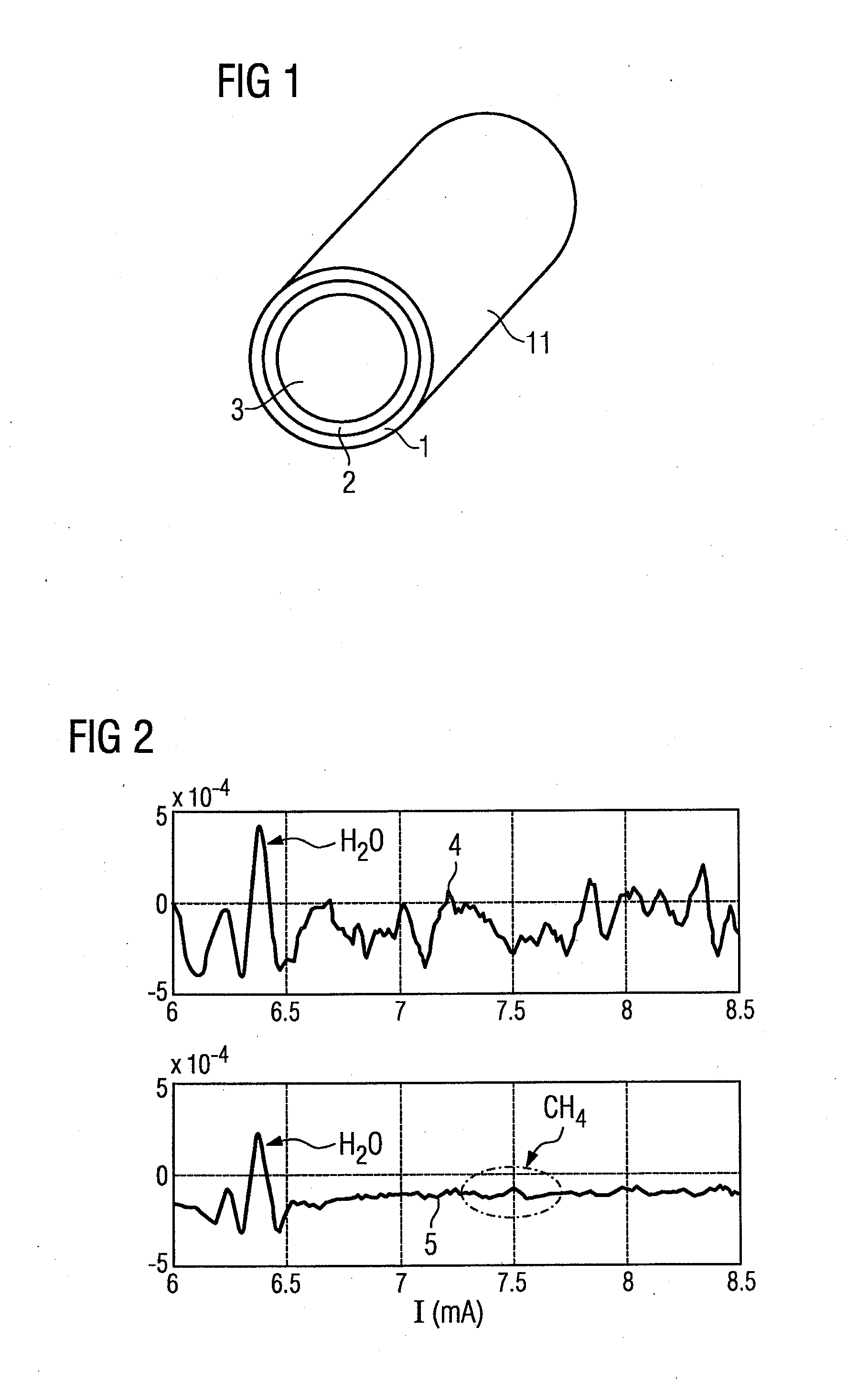
[0021]FIG. 1 shows a simplified schematic layout for a hollow fiber 11 through which the light that will be used for the measurement can be sent. The hollow fiber 11 has an envelope 1 made of silicon dioxide. Within the envelope 1 there is a layer 2 of Ag and / or AgI. The inner space 3 is hollow and filled with air or other gases. Since the light essentially moves in the inner space 3 of the hollow fiber 11, the gas to be found there is measured.

[0022]FIG. 2 shows a comparison between a first measurement 4 without and a second measurement 5 with vibrations of the hollow fiber 11. It can clearly be seen here that the strongly vibrating background created partly by interferences in the first measurement 4 without vibration of the hollow fiber 11 can cause major disruption to the evaluation. In the second measurement 5 with vibration of the hollow fiber 11 on the other hand, except for the absorption lines (in the second derivation) caused by water, at a laser current of between 6 and 6...


PUM

PropertyMeasurementUnit
wavelengthsaaaaaaaaaa
frequencyaaaaaaaaaa

Abstract

An optical gas measurement using a Vertical Cavity Surface-Emitting Laser (VCSEL) and a hollow waveguide connected thereto, wherein the hollow waveguide contains a gas to be measured and conducts light. To this end, the hollow waveguide is made to vibrate. The gas measurement is performed and integrated over a period of time. As a result, disturbances of the measurement caused by interferences are considerably reduced.

Description

CROSS-REFERENCE TO RELATED APPLICATIONS[0001]This is a U.S. national stage of application No. PCT / EP2010 / 062919 filed 3 Sep. 2010. Priority is claimed on German Application No. 10 2009 040 122.9 filed 4 Sep. 2009, the content of which is incorporated herein by reference in its entirety.BACKGROUND OF THE INVENTION[0002]1. Field of the Invention[0003]The invention relates to optical gas measurements and, more particularly, to an optical gas sensor and a method for its operation, where light emitted from a light source is guided through a hollow optical wave guide.[0004]2. Description of the Related Art[0005]Typically, optical gas sensors use a laser diode to emit light in a measurement volume for instance. Here, the measurement volume can be represented in an embodiment of such sensors by a hollow optical wave guide. The hollow optical wave guide guides the light along its extent, if necessary also around bends, and exits the light out or reflects the light at its end to a detector.[0...

Claims


Application Information

Patent Timeline
Patent Type & Authority Applications(United States)
IPC IPC(8): G01N21/61
CPCG01N21/3504G01N21/61G02B6/032G01N2021/0346
Inventor CHEN, JIAHANGAUER, ANDREASSTRZODA, RAINER
Owner SIEMENS AG
Why Eureka
Try Eureka