Coated article with low-e coating having barrier layer system(s) including multiple dielectric layers, and/or methods of making the same

a technology of barrier layer and dielectric layer, which is applied in the direction of vacuum evaporation coating, transportation and packaging, and units with parallel planes, etc., can solve the problems of difficult to achieve, corrosion or other forms of damage to silver-based layers,

Inactive Publication Date: 2013-06-27
GUARDIAN EURO S A R L
View PDF1 Cites 44 Cited by
  • Summary
  • Abstract
  • Description
  • Claims
  • Application Information

AI Technical Summary

Benefits of technology

[0005]It is known to use dielectric thin film layers including materials such as, for example, zirconium oxide, silicon nitride, and the like to help protect against environmental conditions. Unfortunately, however, there oftentimes is a challenge to balance durability with desired optical properties (including, for example, visible transmission, reflection, color, etc.).
[0006]One common approach is to use bottom-most and upper-most layers in a thin film layer stack for durability purposes. For instance, a bottom-most layer comprising silicon nitride may help reduce the occurrence of sodium migration from the underlying substrate into the layer stack, and an upper-most layer comprising zirconium oxide may help provide scratch resistance. Other dielectric layers above and / or below the silver-based layer oftentimes are used in an effort to achieve the desired optical properties.

Problems solved by technology

Low-E coatings oftentimes include silver-based layers, and these silver-based layers are subject to corrosion or other forms of damage when located in harsh environments.
Unfortunately, however, there oftentimes is a challenge to balance durability with desired optical properties (including, for example, visible transmission, reflection, color, etc.).

Method used


Image

  • Coated article with low-e coating having barrier layer system(s) including multiple dielectric layers, and/or methods of making the same
  • Coated article with low-e coating having barrier layer system(s) including multiple dielectric layers, and/or methods of making the same
  • Coated article with low-e coating having barrier layer system(s) including multiple dielectric layers, and/or methods of making the same

Examples


Embodiment Construction

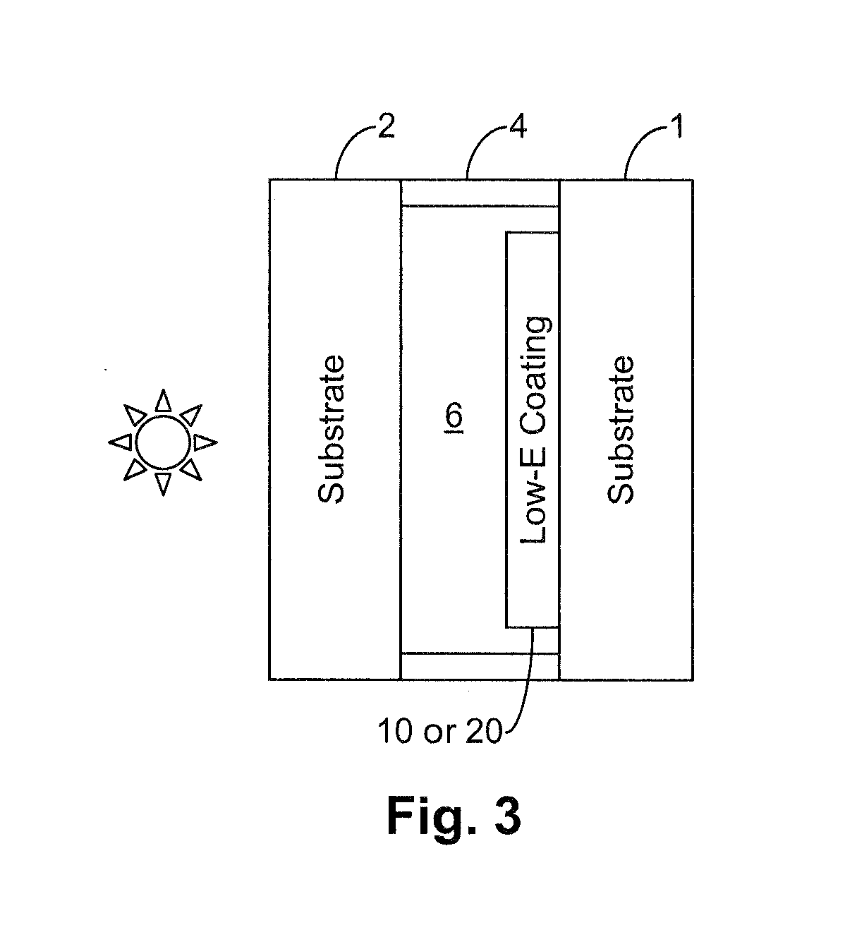
[0023]Coated articles herein may be used in applications such as IG window units, vehicle windows, monolithic architectural windows, residential windows, and / or any other suitable application that includes single or multiple glass substrates.

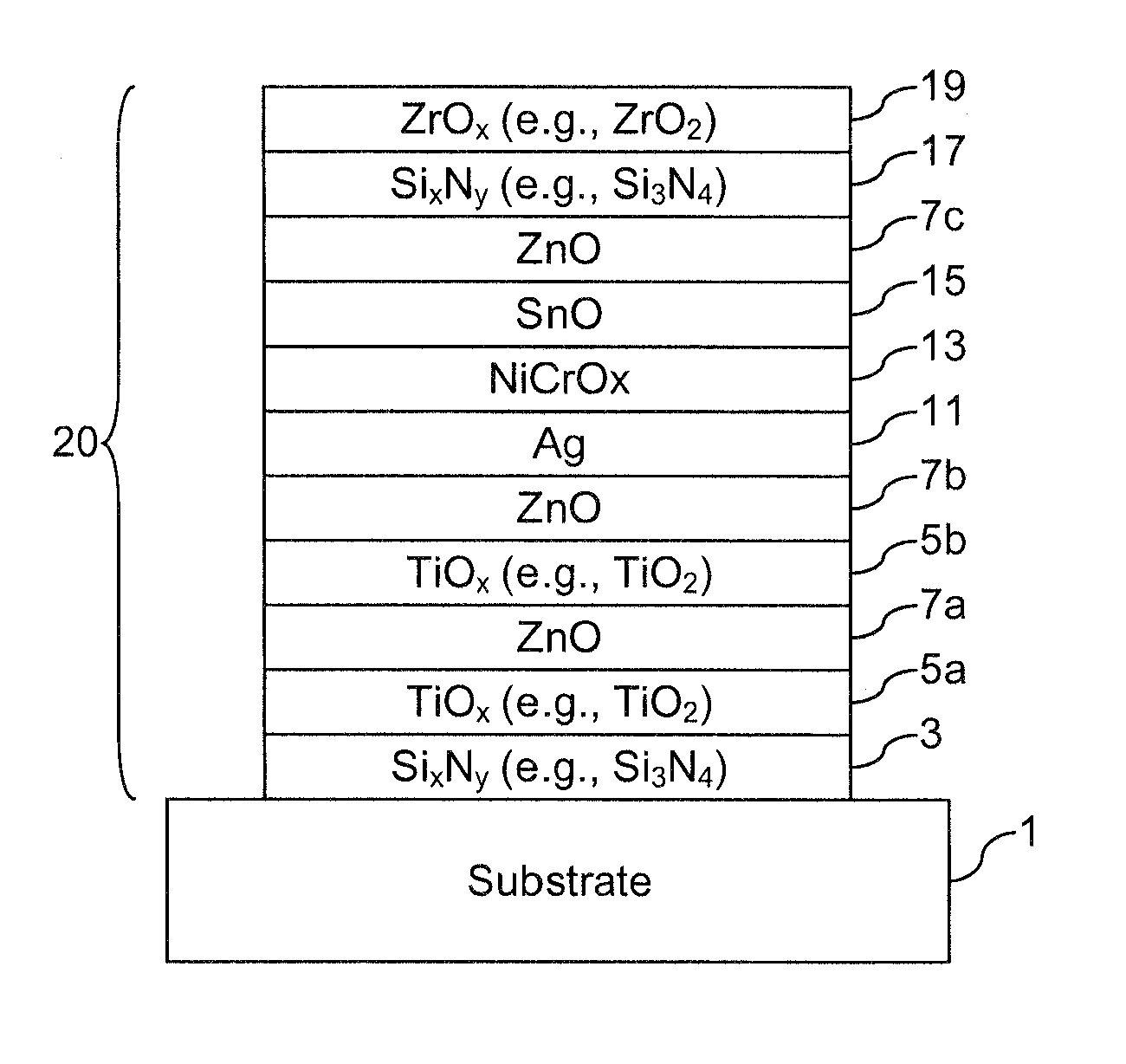
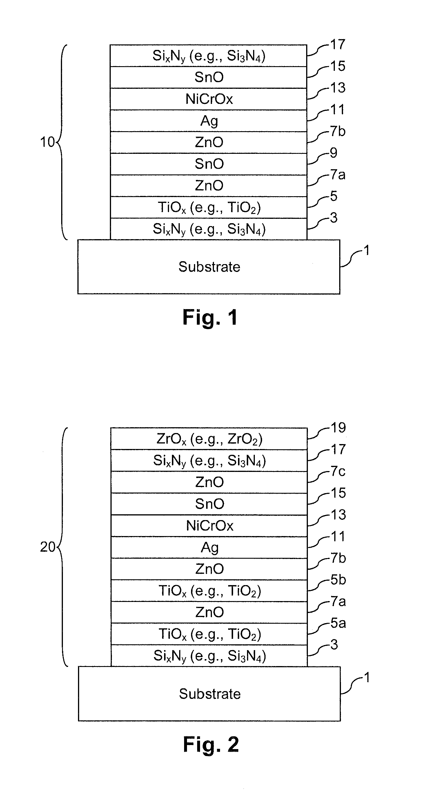
[0024]In certain example embodiments of this invention, the coating includes a single-silver stack, although this invention is not so limited in all instances. For instance, other example embodiments may include double-, triple-, or quadruple silver layer stacks.

[0025]The terms “heat treatment” and “heat treating” as used herein mean heating the article to a temperature sufficient to achieve thermal tempering, heat bending, and / or heat strengthening of the glass inclusive article. This definition includes, for example, heating a coated article in an oven or furnace at a temperature of least about 580 degrees C., more preferably at least about 600 degrees C., for a sufficient period to allow tempering, bending, and / or heat strengthening. In certa...


PUM

PropertyMeasurementUnit
thicknessaaaaaaaaaa
thicknessaaaaaaaaaa
thicknessaaaaaaaaaa

Abstract

Certain example embodiments of this invention relate to coated articles with low-E coatings having one or more barrier layer systems including multiple dielectric layers, and/or methods of making the same. In certain example embodiments, providing barrier layer systems that each include three or more adjacent dielectric layers advantageously increases layer quality, mechanical durability, corrosion resistance, and/or thermal stability, e.g., by virtue of the increased number of interfaces. These barrier layer systems may be provided above and/or below an infrared (IR) reflecting layer in the low-E coating in different embodiments. Coated articles according to certain example embodiments of this invention may be used in the context of insulating glass (IG) window units, vehicle windows, other types of windows, or in any other suitable application.

Description

FIELD OF THE INVENTION[0001]Certain example embodiments of this invention relate to coated articles including low-E coatings, and / or methods of making the same. More particularly, certain example embodiments relate to coated articles with low-E coatings having one or more barrier layer systems including multiple dielectric layers, and / or methods of making the same. In certain example embodiments, providing barrier layer systems including multiple dielectric layers advantageously increases layer quality, mechanical durability, corrosion resistance, and / or thermal stability. Coated articles according to certain example embodiments of this invention may be used in the context of insulating glass (IG) window units, vehicle windows, other types of windows, or in any other suitable application.BACKGROUND AND SUMMARY OF EXAMPLE EMBODIMENTS OF THE INVENTION[0002]Coated articles are known in the art for use in window applications such as insulating glass (IG) window units, vehicle windows, a...

Claims


Application Information

Patent Timeline
Patent Type & Authority Applications(United States)
IPC IPC(8): B32B17/06E06B3/673B05D5/06C23C14/34B32B3/00E06B3/66
CPCC03C17/36C03C17/3618C03C17/3626Y10T428/2495C03C17/366C03C17/3681C03C2218/155C03C17/3644B32B17/061E06B3/66E06B3/6715C09D5/004
Inventor LAGE, HERBERTFERREIRA, JOSEPALLOTTA, PIERRE
Owner GUARDIAN EURO S A R L
Why Eureka
Try Eureka