Balloon catheter

a balloon catheter and balloon technology, applied in the field of balloon catheters, can solve the problems of difficult retention of balloons, difficult selection of only the target, and cicatricial contraction of the entire inner circumference of the luminal organ, and achieve the effect of efficient ablation of target tissu

Inactive Publication Date: 2013-06-27
JAPAN ELECTEL
View PDF6 Cites 8 Cited by
  • Summary
  • Abstract
  • Description
  • Claims
  • Application Information

AI Technical Summary

Benefits of technology

[0028]According to the tenth aspect of the present invention, even if the balloon catheter receives a flow such as a blood flow from the distal end side thereof in a luminal organ, since the gas space...

Problems solved by technology

This ablation, however, has a risk of causing a cicatricial contraction on the entire inner circumference of the luminal organ and a functional incompetence due to its stenosis.
According to the balloon catheter employing the...

Method used


Image

  • Balloon catheter
  • Balloon catheter
  • Balloon catheter

Examples


first embodiment

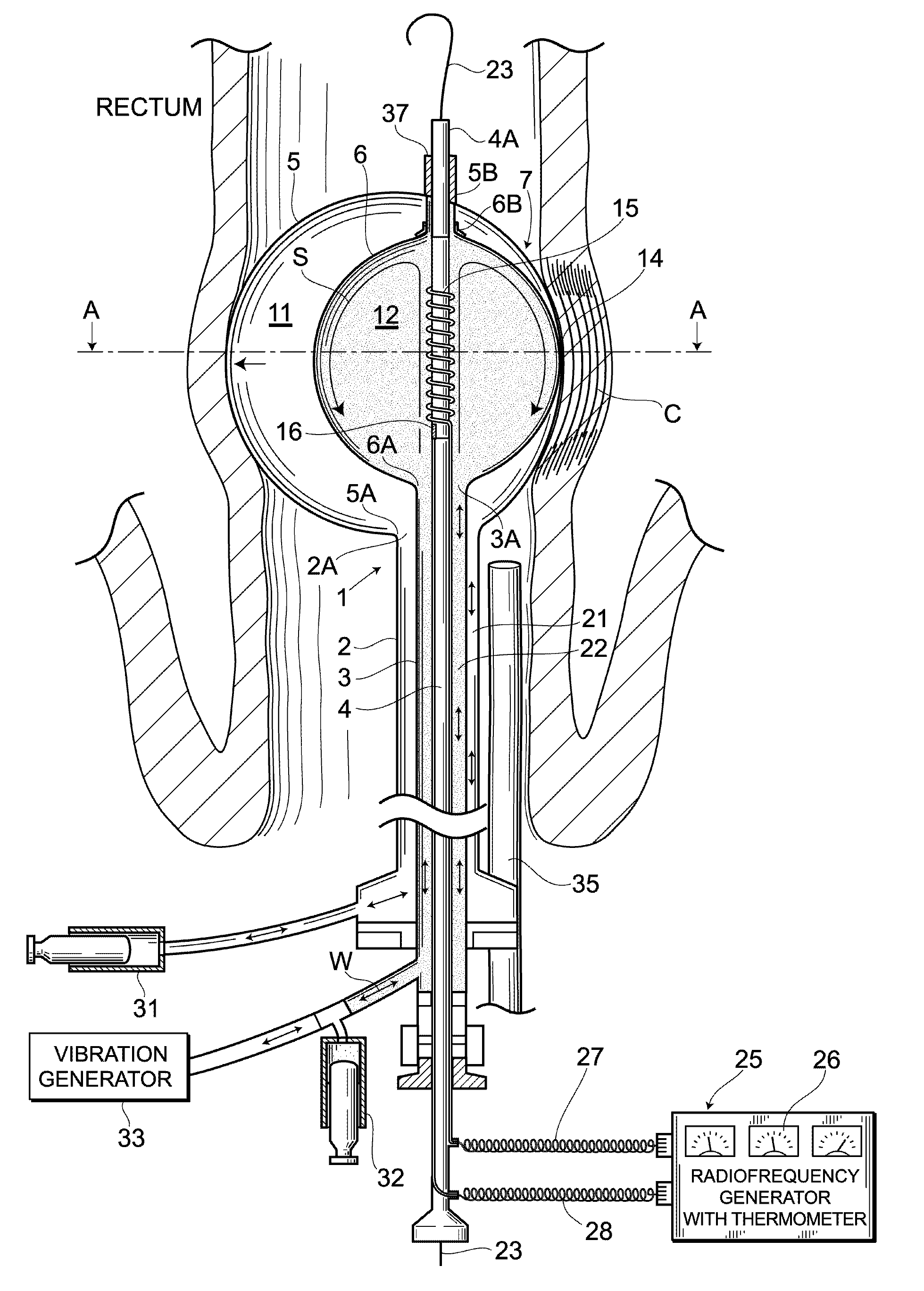
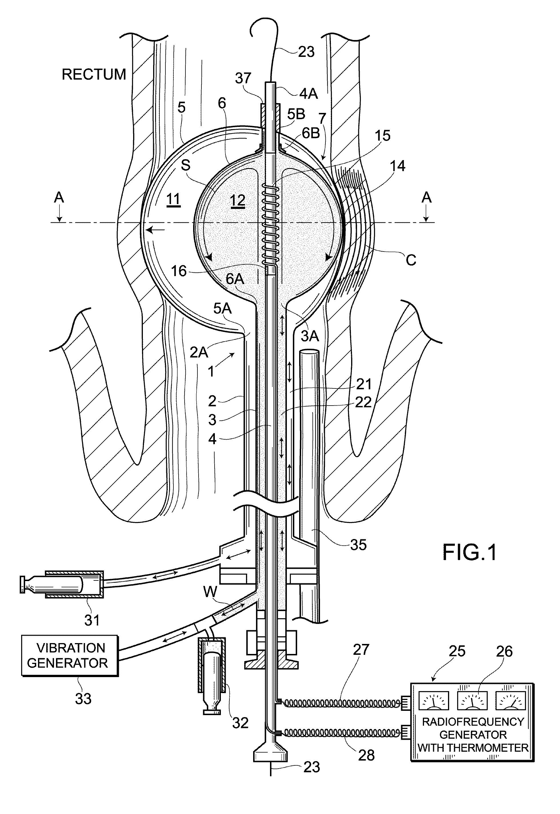
[0035]FIG. 1 and FIG. 2 show a balloon catheter in a first embodiment of the present invention. In these figures, numeral symbol 1 denotes a cylindrical catheter shaft which is insertable into a luminal organ and is richly flexible. The catheter shaft 1 includes an outer tube 2, an intermediary tube 3 and an inner tube 4, which are slidable to each other. An outer balloon 5 including an outer surface exposed to the outside is provided between a distal end 2A of the outer tube 2 and a vicinity of a distal end 4A of the inner tube 4. An inner balloon 6 whose outer surface is surrounded with the outer balloon 5 is provided between a distal end 3A of the intermediary tube 3 and the vicinity of the distal end 4A of the inner tube 4. A balloon part 7 including the structure of a balloon inside a balloon, that is a duplex structure of the outer and inner balloons 5, 6, is provided on the distal end side of the catheter shaft 1.

[0036]An internal space between an inner surface of the outer b...

second embodiment

[0055]FIG. 3 shows a balloon catheter according to a second embodiment of the present invention. According to the balloon part 7 of the present embodiment, not only a straight line connecting the tube coupling openings 6A, 6B coincides with the central line of the inner balloon 6 inflating into an substantially spherical shape but also a straight line connecting the tube coupling openings 5A, 5B coincides with the central line of the outer balloon 5 inflating into an substantially gourd shape or an substantially bale shape. Further, with the outer and inner balloons 5, 6 inflated, on a circumference in a radial direction of the balloon part 7, a close-contact portion 14 is formed where the outer and inner balloons 5, 6 can be partially closely contacted by each other.

[0056]The outer balloon 5 and the inner balloon 6 may be different in shape as in the present embodiment, and further with the outer and inner balloons 5, 6 inflated, when the outer balloon 5 is pressed against the insi...

third embodiment

[0061]FIG. 4 shows a balloon catheter according to a third embodiment of the present invention. As with the first embodiment, in the balloon part 7 in the present embodiment, a straight line connecting the tube coupling openings 6A, 6B of the inner balloon 6 coincides with the central line of the inner balloon 6, while a straight line connecting the tube coupling openings 5A, 5B is deviated from the central line of the outer balloon 5. Note that, however, whilst the outer balloon 5 is spherical as is the case in the inner balloon 6 in the first embodiment, the inner balloon 6 is spherical and the outer balloon 5 is oblate in form in the present embodiment. Other structures are in common with those in the first embodiment.

[0062]Next is a description of how to use the balloon catheter according to the present embodiment. FIG. 4 shows an example of the application of the balloon catheter to a treatment of a hypertrophy of prostate medial lobe.

[0063]The conventional devices utilizing mi...


PUM


Abstract

Thermal conduction to a non-target tissue is unfailingly blocked off to select and effectively ablate only a target tissue. A catheter shaft 1 includes an outer, intermediary and inner tubes 2, 3, 4 which are slidable to each other. An outer balloon 5 is arranged between distal ends 2A, 4A of the outer and inner tubes 4, 5, while an inner balloon 6 is arranged between distal ends 3A, 4A of the intermediary and inner tube 4. The outer balloon 5 is filled with a low thermal conductive gas. Filling solution filled inside the inner balloon 6 is subjected to radiofrequency heating by supplying electricity to an electrode. The outer balloon 5 is held inside a luminal organ and the thermal conduction from the inner balloon 6 is blocked off, thus the thermal energy of the inner balloon 6 selectively ablates a target tissue via a close-contact portion 14.

Description

BACKGROUND OF THE INVENTION[0001]1. Field of the invention[0002]The present invention relates to a balloon catheter for radiofrequency thermal therapy, which is inserted into a luminal organ to selectively ablate a target tissue such as a site of lesion at optimal temperature.[0003]2. Description of the Related Art[0004]The conventional radiofrequency thermal balloon catheter includes a balloon provided with an electrode for delivery of a radiofrequency current therein. The radiofrequency current is applied to the electrode for delivery of radiofrequency current and thus a solution inside of the balloon is heated to raise a surface temperature of the balloon and then the tissue in contact with the balloon is directly ablated. When inserting the balloon catheter into a luminal organ such as a blood vessel, an esophagus, or a large intestine to treat them, it was common for the tissue in contact with the balloon to be ablated circumferentially. This ablation, however, has a risk of ca...

Claims


Application Information

Patent Timeline
IPC IPC(8): A61B18/18
CPCA61B18/1492A61B2018/00017A61B2018/0016A61B2018/046A61B2018/00255A61B2018/044A61B2018/0019
Inventor SATAKE, SHUTARO
Owner JAPAN ELECTEL
Why Eureka
Try Eureka