Work vehicle fluid heating system

Inactive Publication Date: 2013-07-04
CNH IND AMERICA LLC
View PDF8 Cites 7 Cited by
  • Summary
  • Abstract
  • Description
  • Claims
  • Application Information

AI Technical Summary

Benefits of technology

The present invention has the advantage of quickly warming hydraulic oil in a hydraulic circuit, without needing the implement or operator to move. This allows for faster and more efficient operation of the hydraulic system.

Problems solved by technology

This oil can be heated by the operator manually by cycling the loader circuit, but this activity can be both fatiguing and time-consuming to the operator.
A drawback of a fixed-flow cooling fan circuit is that it is pressure-controlled.
In response to an increase in the pressure in the cooling fan circuit, the speed of the cooling fan likewise increases, providing undesirable cooling to the same hydraulic oil that is to be heated.
In other words, it has not been possible to generate a high system pressure (which would most quickly heat the oil) without also operating the cooling fan at a high speed.

Method used


Image

  • Work vehicle fluid heating system
  • Work vehicle fluid heating system
  • Work vehicle fluid heating system

Examples


Embodiment Construction

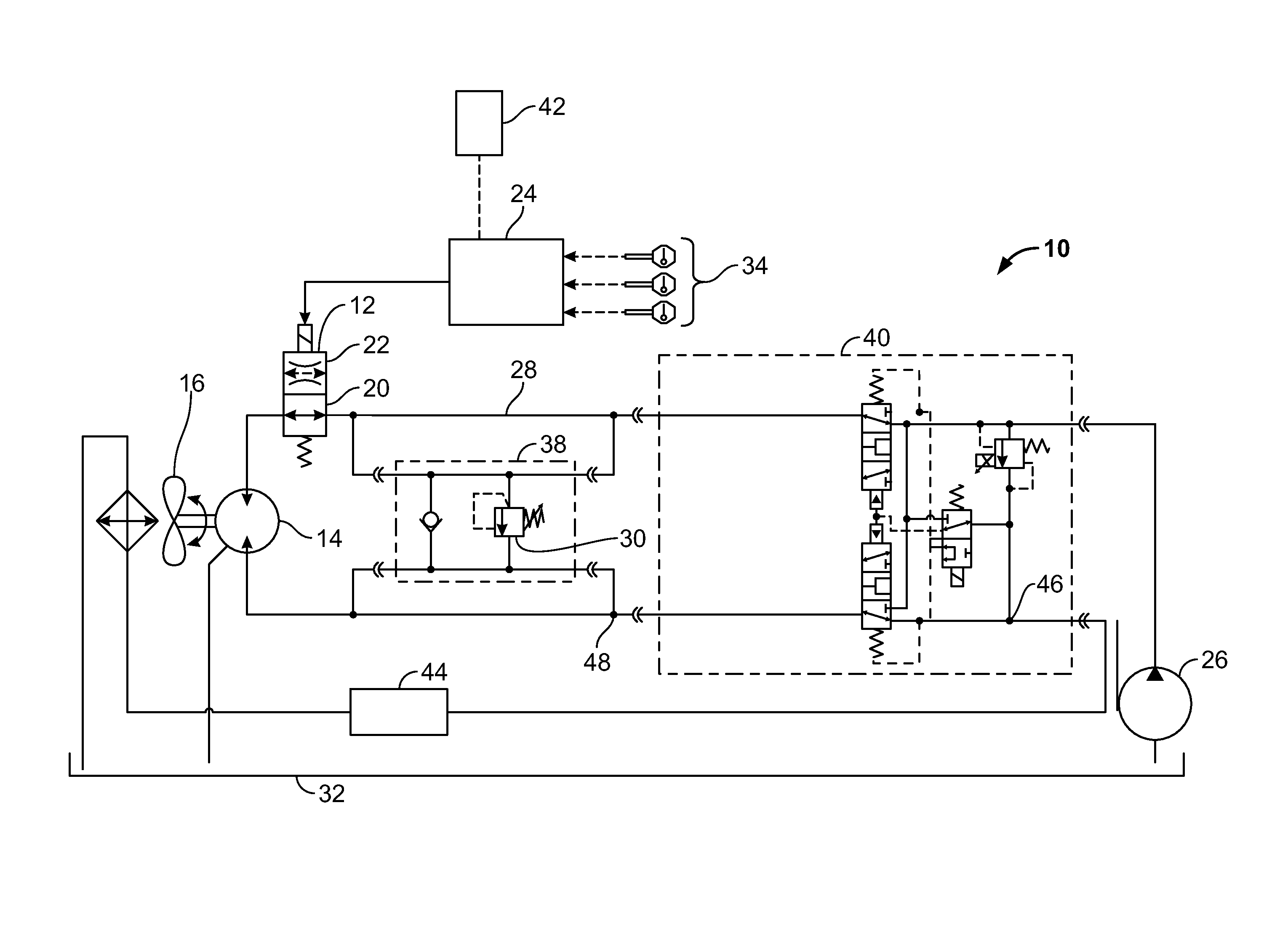
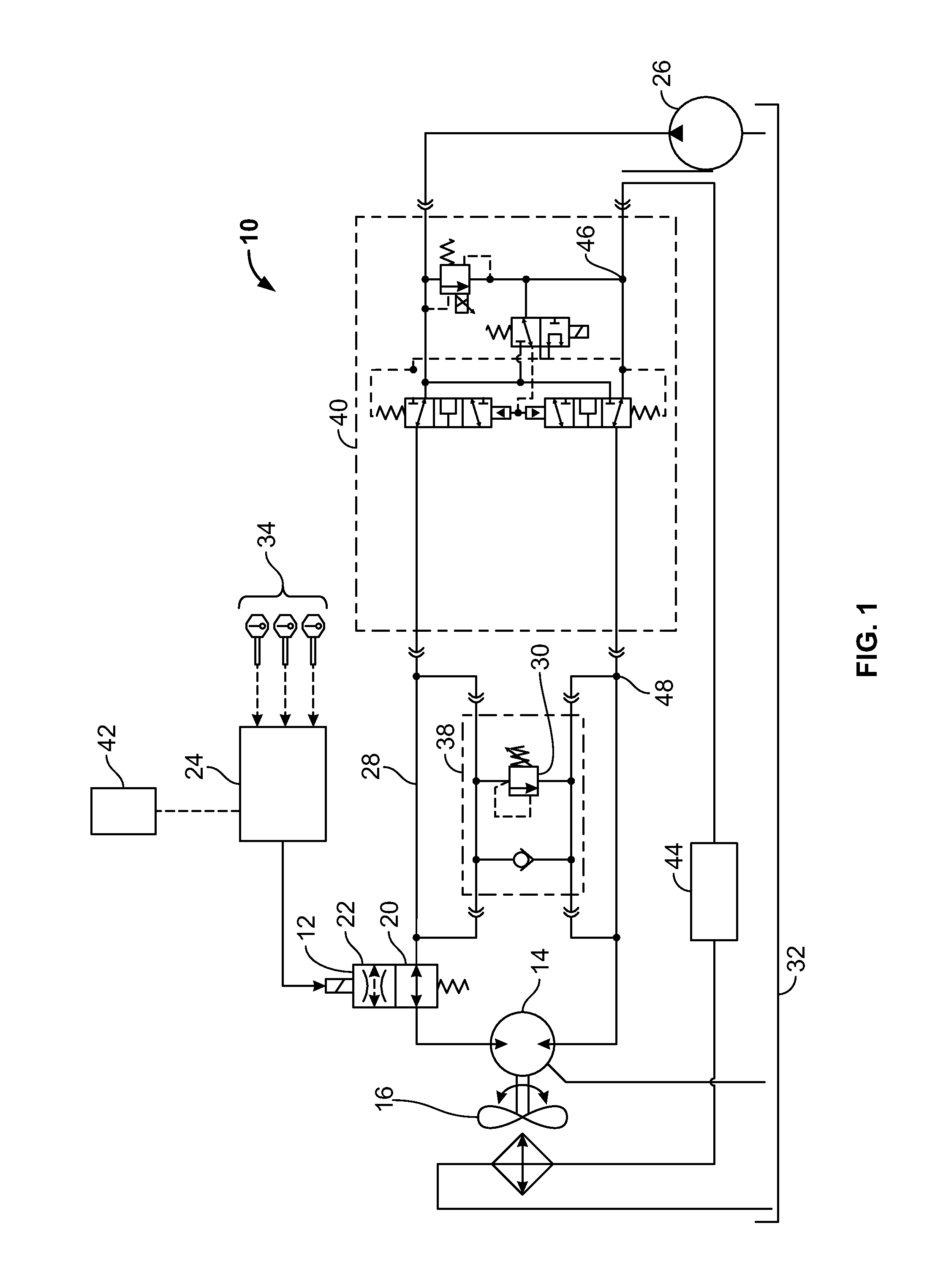
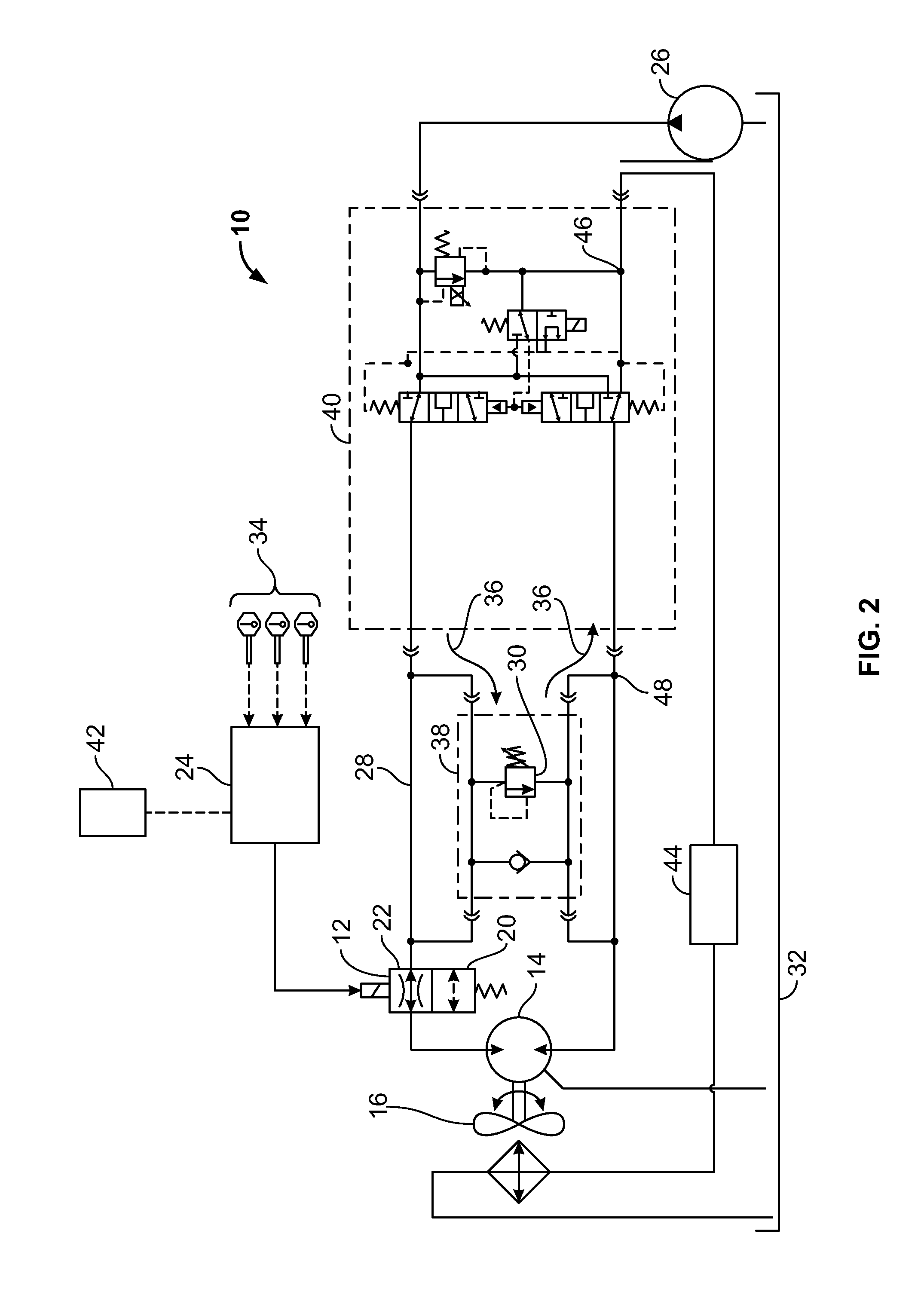
[0014]Referring to the drawings, FIGS. 1-2 show schematic representations of an exemplary embodiment of the present disclosure. FIG. 1 shows a fluid heating system 10 including a control device 12, such as a digitally controlled solenoid valve having a first position 20 and a second position 22. Control device 12 is controlled by a control module 24 that receives input signals from sensors 34 associated with temperatures and / or other component / system / subsystem operating parameters. Under normal operating conditions, such as when the ambient temperature is greater than a predetermined minimum temperature, such as 90° C. in one application, and in combination with other parameters in other applications such as discussed in further detail below, hydraulic pump 26 provides pressurized hydraulic oil to a fluid circuit 28. In response to sensors 34 controlled by control module 24 sensing the temperature of the hydraulic oil in fluid circuit 28, as well as other temperature / parameters as d...


PUM


Abstract

A fluid heating system for a work vehicle including a pressurized fluid circuit, a pump, and a fan for cooling fluid of the fluid circuit. Pressurized fluid of the fluid circuit provided to the fan results in fan operation. A speed of the fan corresponds to a flow rate of pressurized fluid of the fluid circuit provided to the fan. A control device is in fluid communication with the fluid circuit, the control device operable between a first position and a second position. The first position of the control device results in substantially all of the fluid of the fluid circuit being provided to the fan. The second position of the control device results in at least a portion of the fluid of the fluid circuit bypassing the fan, thereby reducing the speed of the fan while increasing a pressure magnitude and increasing a temperature of the fluid system.

Description

FIELD OF THE INVENTION[0001]This invention relates generally to fluid heating systems, and the use thereof, and, more particularly, to vehicle fluid heating systems.BACKGROUND OF THE INVENTION[0002]In cold climates, it is important to minimize the amount of time needed to warm a vehicle to operating temperature. More specifically, the temperature of the hydraulic oil must be increased to a minimum operating temperature before implement operation, such as a loader, is allowed. This oil can be heated by the operator manually by cycling the loader circuit, but this activity can be both fatiguing and time-consuming to the operator. Alternatively, the vehicle could include a system or arrangement on the vehicle to warm the hydraulic oil already being automatically circulated, such as with a fixed-flow cooling fan circuit.[0003]A drawback of a fixed-flow cooling fan circuit is that it is pressure-controlled. That is, a fixed amount of flow supplies the circuit via a gear pump, and a varia...

Claims


Application Information

Patent Timeline
IPC IPC(8): F28F27/00F15B21/0427
CPCF15B21/042B60H1/22F28F27/00E02F9/2228F01N2610/10E02F9/2296B60H1/00314F01N3/2066E02F9/226F15B21/0427Y02A50/20
Inventor DEAN, PATRICKNATZKE, DAVID R.JOHNSON, BRADBERARD, CRAIG
Owner CNH IND AMERICA LLC
Why Eureka
Try Eureka