Photonic system and method for tunable beamforming of the electric field radiated by a phased array antenna

a phased array antenna and photonic technology, applied in the direction of rf signal generation/processing, fiber transmission, electrical transmission, etc., can solve the problems of reducing bandwidth, reducing the efficiency of tunable time delay electrical implementation, and increasing the insertion loss

Active Publication Date: 2013-07-04
INST DE TELECOMUNICACOES
View PDF3 Cites 19 Cited by
  • Summary
  • Abstract
  • Description
  • Claims
  • Application Information

AI Technical Summary

Problems solved by technology

Since there are many applications with high bandwidth (e.g., RADAR signals, Gb/s wireless networks, radio astronomy, etc.), the beamforming of the radiated electric field cannot be efficiently performed with such a technique.
The electrical implementation of a tunable time delay is particularly challenging at high frequencies, since increasing time delays implies increasing the length of the delay line, which in turn leads to greater ins

Method used


Image

  • Photonic system and method for tunable beamforming of the electric field radiated by a phased array antenna
  • Photonic system and method for tunable beamforming of the electric field radiated by a phased array antenna
  • Photonic system and method for tunable beamforming of the electric field radiated by a phased array antenna

Examples


second embodiment

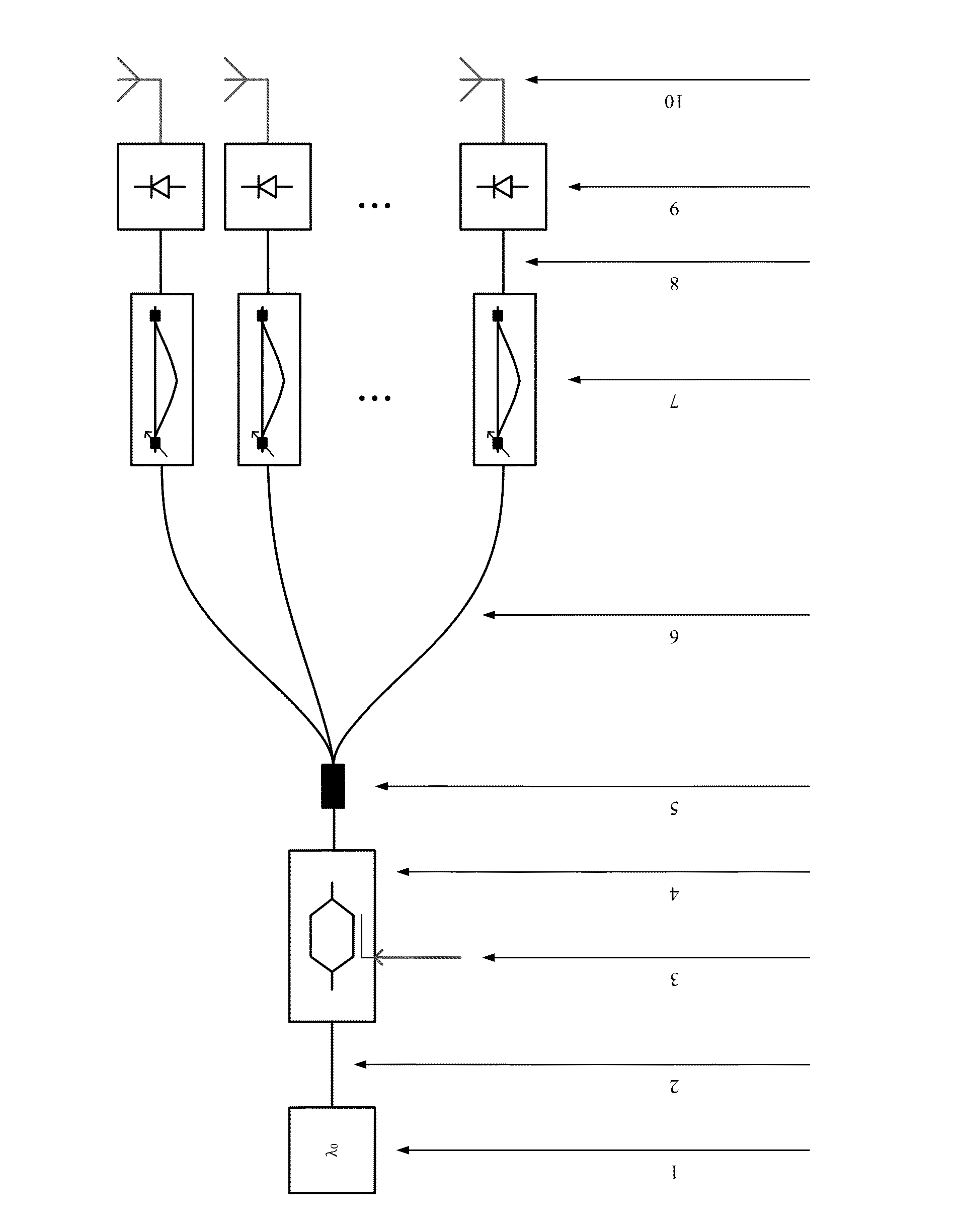
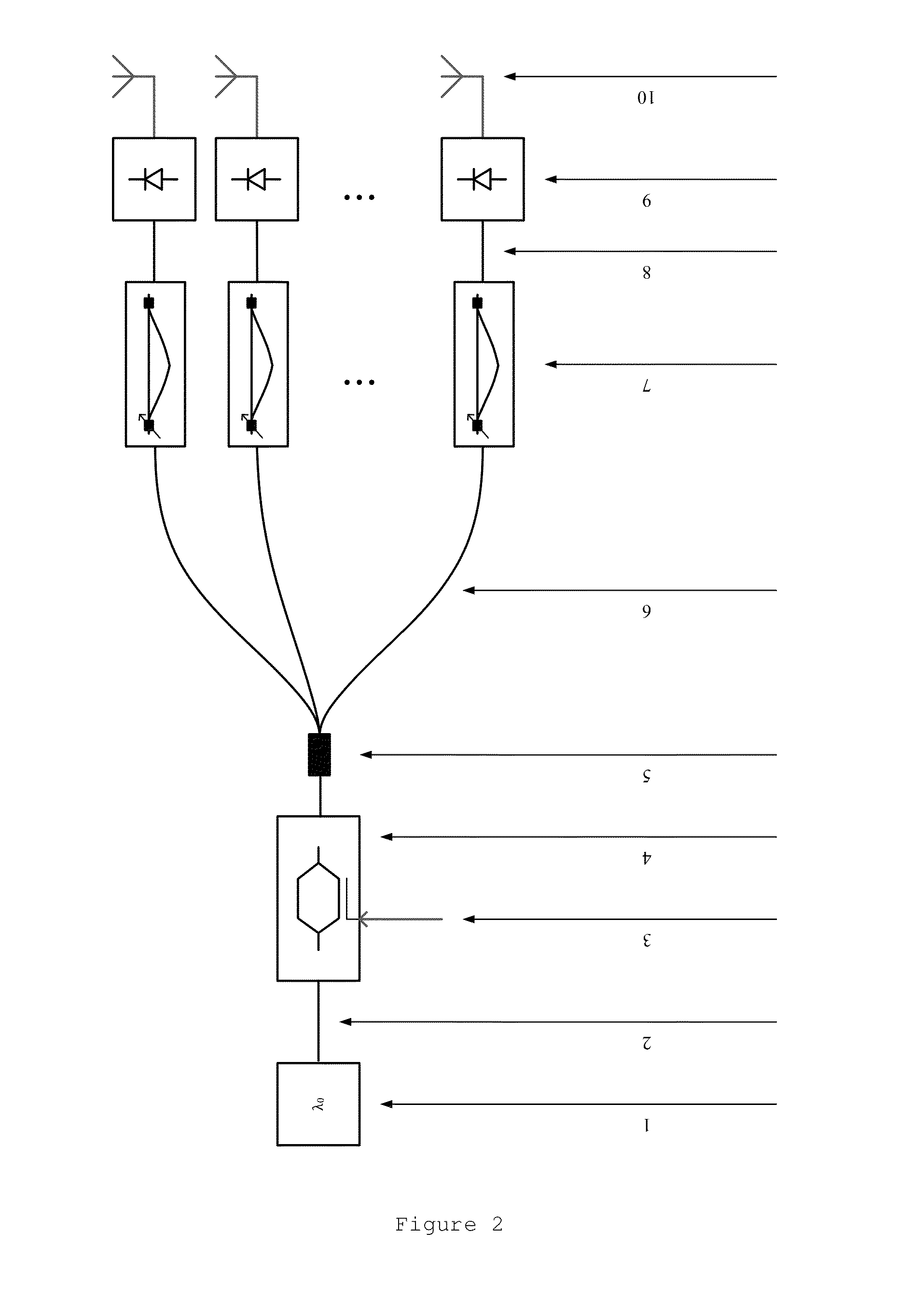
[0026]The second embodiment is shown in FIG. 3. This embodiment also comprises a ML source (1), optical connections (2), (6), (8), an electro-optic modulator (4), a 1 to N optical signal splitter (5), N photodetectors (9) and N antennas (10). The new components are PC's (12), (16), a birefringent medium (14), N polarizers (18), and additional optical connections (11), (13), (15) and (17). This embodiment is essentially an optimized version of the embodiment depicted in FIG. 2. Instead of the N independent MZDI's (7), the N interferometers of this embodiment share the input optical coupler. The modulated optical signal has a linear polarization state at the output of the electro-optic modulator (4). The birefringent medium (14) allows propagation of an optical signal along two orthogonal polarization axes, which have different propagation velocities. Therefore, this medium allows obtaining a time delay i between two orthogonally polarized optical signals aligned with the orthogonal p...

third embodiment

[0027]The third embodiment is shown in FIG. 4. This embodiment comprises N ML sources (19) optically connected to N PC's (21). The signals generated by the N ML sources are multiplexed in the wavelength, using a wavelength multiplexer (23) which is optically connected to the electro-optic modulator (4). All multiplexed signals are modulated the same way, and then introduced into the birefringent medium (14). The multiplexed signals at the output of the birefringent medium are now de-multiplexed using a wavelength de-multiplexer (24) with N outputs, where each one of the N outputs is connected to a PC (16) and a polarizer (18). Several optical connections are presented at (20), (22), (2), (11), (15), (6), (17) and (8). Of course, the N photodetectors (9) and N elementary antennas (10) are the same as in previously described embodiments. Although previous embodiments are based on a ML source (1) and an optical splitter (5) which is not sensitive to the wavelength, the present embodime...


PUM


Abstract

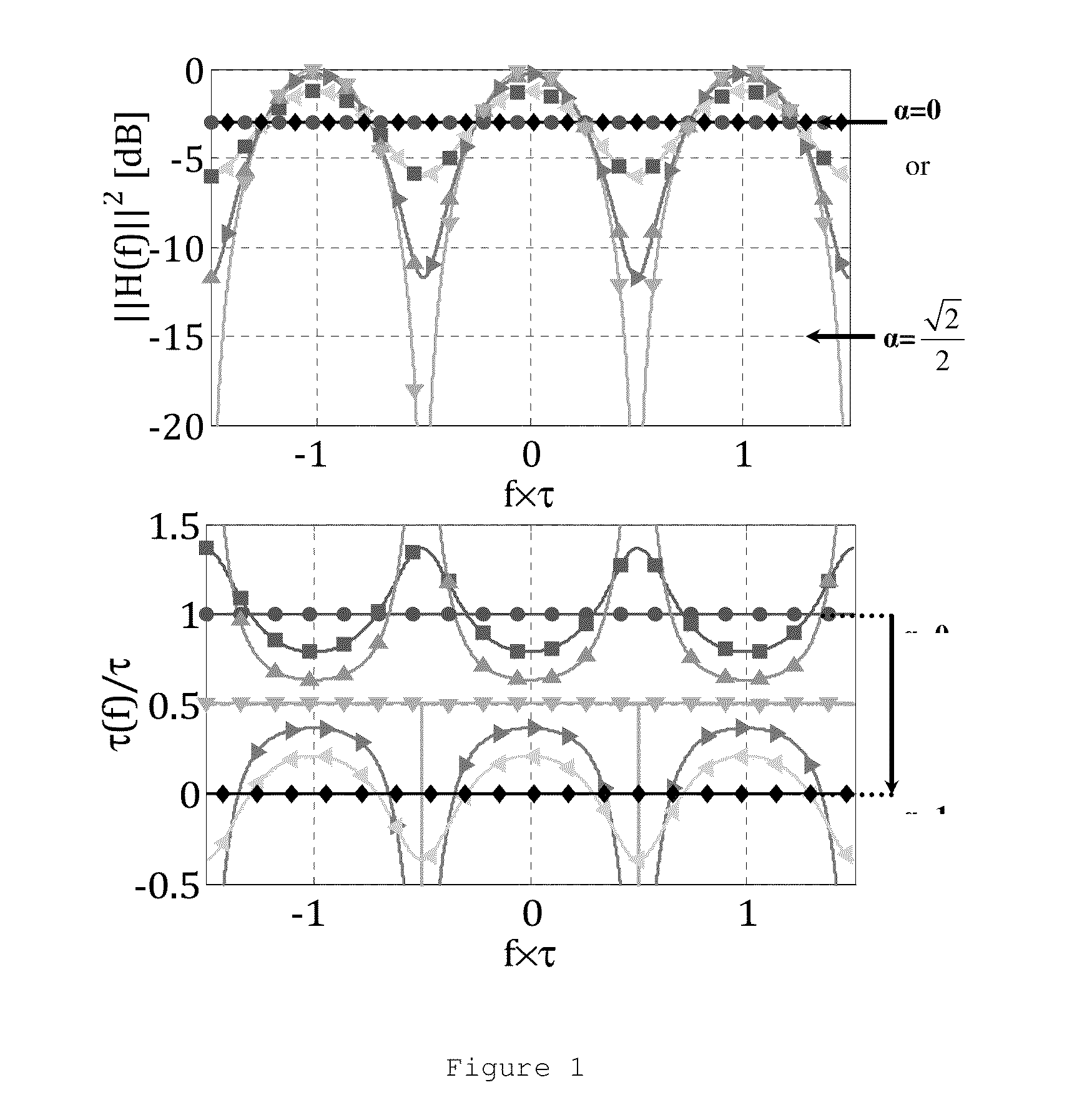
This invention discloses a photonic system to beamform the electric field yield by a phased array antenna. The system function relies on a photonic tunable delay line, which consists on an optical Mach-Zehnder interferometer with a predefined time delay difference between arms. The time delay is tuned by adjusting the coupling ratio between the power applied to each one of the interferometer's delay lines. Three embodiments are proposed, wherein one of them just uses a single delay line and a single monchromatic light source, independently of the quantity of the array elementary antennas.

Description

FIELD OF THE INVENTION[0001]This invention discloses a photonic system and method with the purpose of beamforming the electric field yield by a phased array antenna (PAA). The system relies on a photonic tunable optical delay line (TODL), which is an Mach-Zehnder optical interferometer with a predefined differential time delay between arms. The time delay is tuned by adjusting the coupling ratio between the power applied to each one of the interferometer's delay lines. Three embodiments are proposed, wherein one of them just uses a single delay line and a single monochromatic light (ML) source, independently of the quantity of elementary antennas of the phased array. The application of the described TODL in a photonic system with the purpose of beamforming the electric field yield by a PAA has not been found in the present state of the art. The proposed system is apropriate to wireless communication systems with high frequency RF carriers, which allow handling with high data transmi...

Claims


Application Information

Patent Timeline
IPC IPC(8): H01Q3/26H04B10/2575
CPCH01Q3/2676H01Q3/2682H04B2210/006H04B10/25752
Inventor VIDAL DRUMMOND, MIGUELNUNES NOGUEIRA, ROGERIO
Owner INST DE TELECOMUNICACOES
Why Eureka
Try Eureka