Circular polarization antenna

a technology of circular polarization and antennas, applied in the direction of antennas, slot antennas, electric long antennas, etc., can solve the problems of data loss, phase vertical polarization wave, and the combination of data signals in a constructive or destructive manner

Active Publication Date: 2013-07-04
MEDIATEK INC
View PDF5 Cites 16 Cited by
  • Summary
  • Abstract
  • Description
  • Claims
  • Application Information

AI Technical Summary

Problems solved by technology

In a wireless communication system, data signals may be reflected from many surrounding objects so that the reflected waves may combine with the data signals in a constructive or destructive manner.
Though the dipole antenna can be employed to receive and transmit the vertically polarized waves, multi-path interferenc...

Method used


Image

  • Circular polarization antenna
  • Circular polarization antenna
  • Circular polarization antenna

Examples


Embodiment Construction

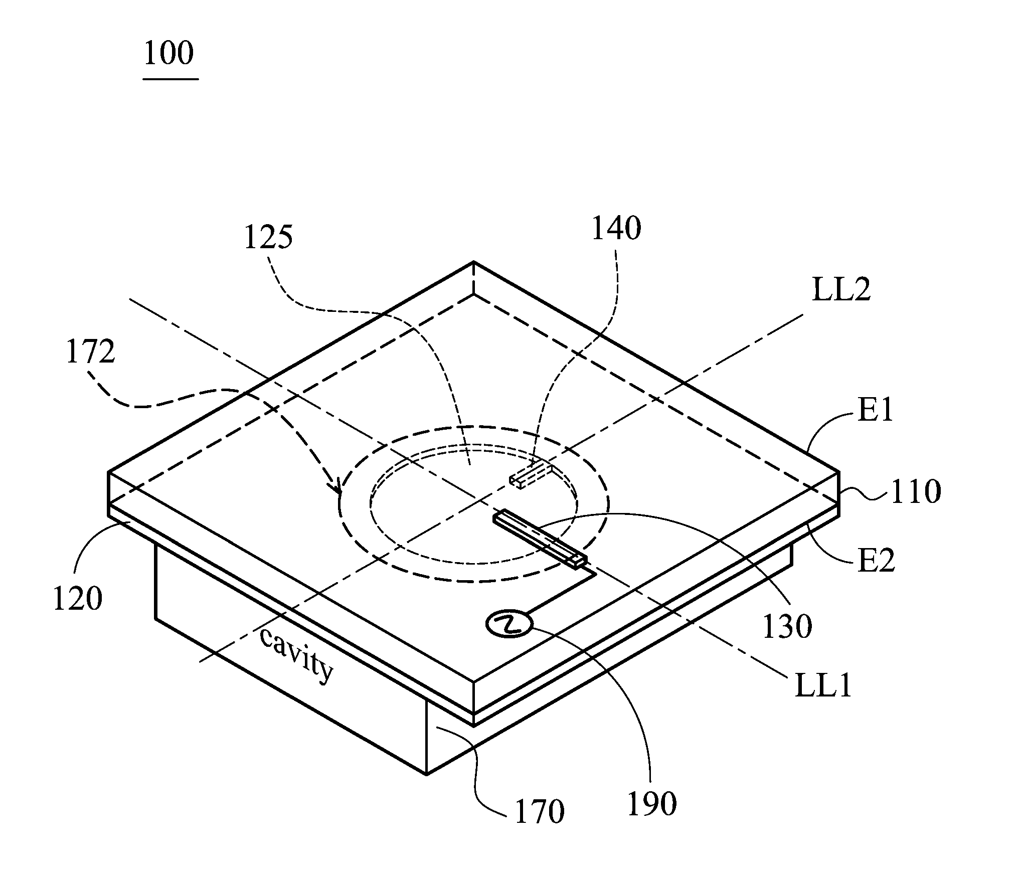
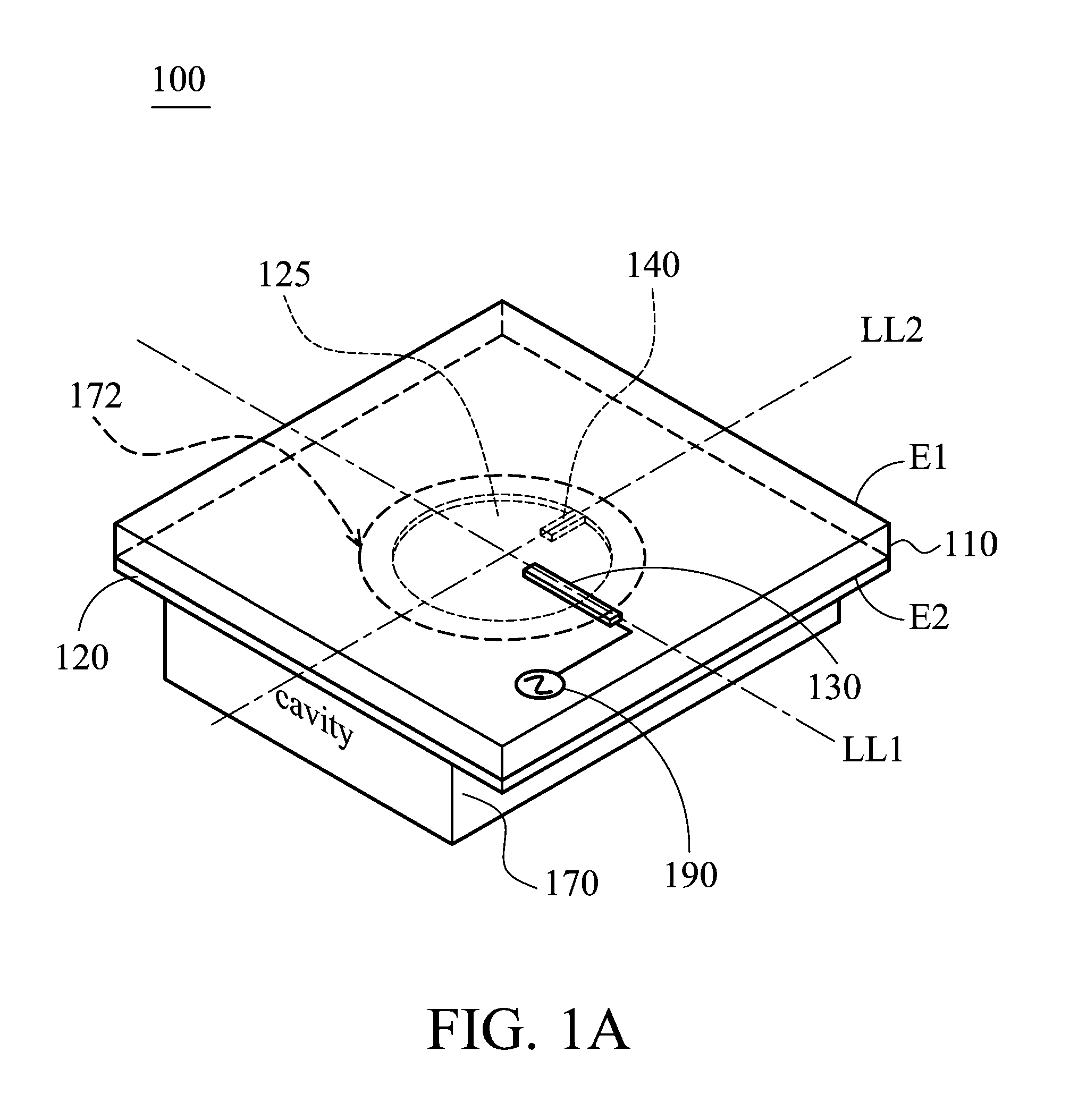
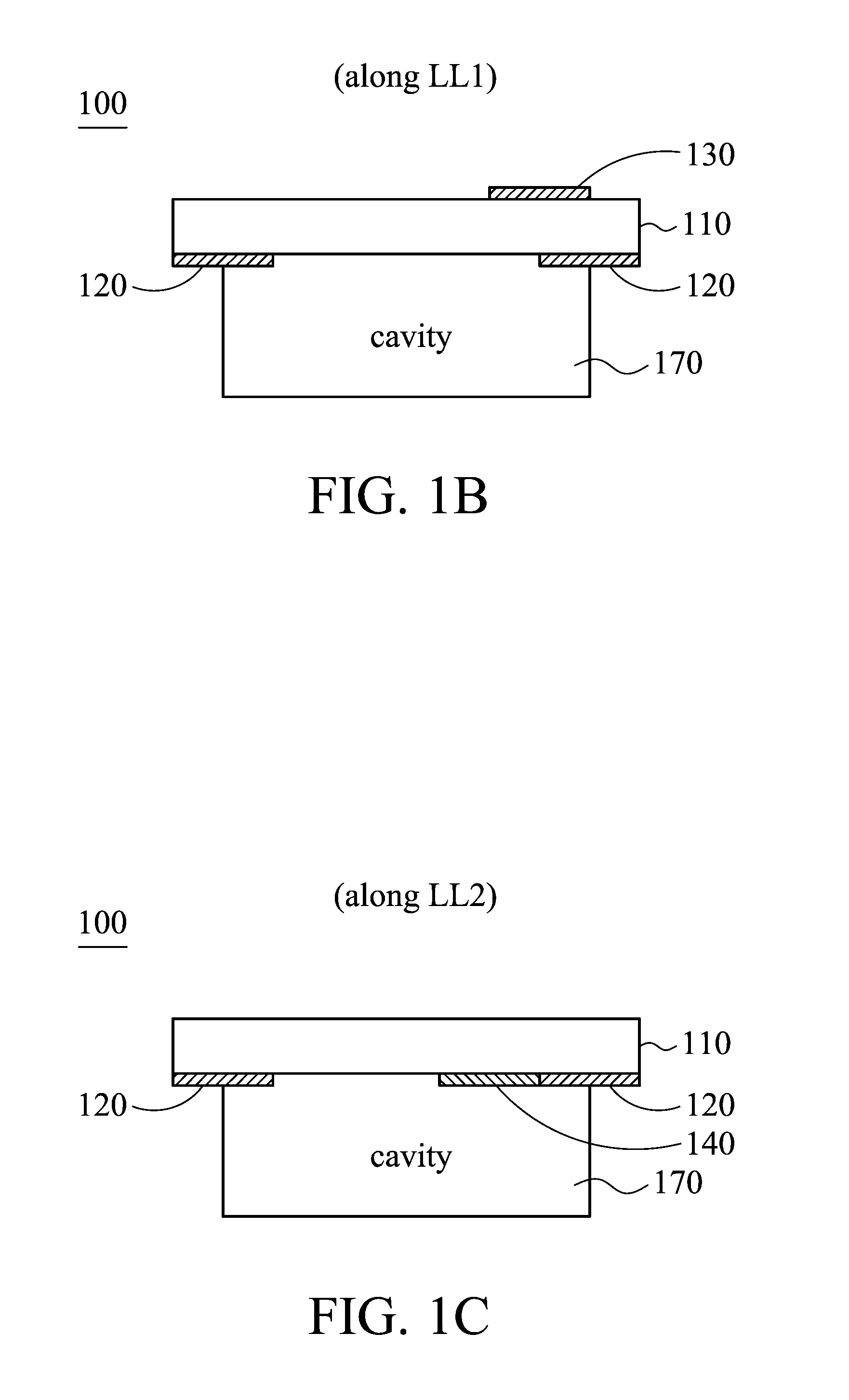
[0031]FIG. 1A is a pictorial drawing for illustrating a circular polarization antenna 100 according to an embodiment of the invention. FIG. 1B is a sectional drawing along a line LL1 for illustrating the circular polarization antenna 100 according to the embodiment of the invention. FIG. 1C is another sectional drawing along another line LL2 for illustrating the circular polarization antenna 100 according to the embodiment of the invention. As shown in FIGS. 1A, 1B and 1C, the circular polarization antenna 100 comprises: a substrate 110, a ground plane 120, a feeding element 130, a tuning stub 140, and a cavity structure 170. The substrate 110 may be an FR4 substrate with a dielectric constant equal to 4.3 and be 0.6 mm in thickness. The ground plane 120, the feeding element 130 and the tuning stub 140 may be made of metal, such as silver or copper.

[0032]The substrate 110 has two surfaces E1 and E2, wherein the surface E1 is opposite to the surface E2. The feeding element 130 is dis...


PUM


Abstract

A circular polarization antenna includes a substrate, a ground plane, a tuning stub, a feeding element, and a cavity structure. The substrate has a first surface and a second surface. The feeding element is disposed on the first surface of the substrate. The ground plane is disposed on the second surface of the substrate and has a hole. The tuning stub is disposed on the second surface of the substrate and connected to the edge of the hole. The cavity structure is connected to the ground plane and configured to reflect an electromagnetic wave.

Description

BACKGROUND OF THE INVENTION[0001]1. Field of the Invention[0002]The disclosure generally relates to a circular polarization antenna, and more particularly, relates to a circular polarization antenna with high antenna gain.[0003]2. Description of the Related Art[0004]With respect to wireless data communications, antennas play an important role for transmitting and receiving electromagnetic waves. Usually, the antennas should be provided with omni-directional radiation patterns in the azimuth direction, and null patterns in the top direction. Therefore, a rod-like antenna, such as a dipole antenna, is considered to be suitable for transmitting and receiving vertically polarized waves and thus is widely applied to communication devices nowadays.[0005]In a wireless communication system, data signals may be reflected from many surrounding objects so that the reflected waves may combine with the data signals in a constructive or destructive manner. Though the dipole antenna can be employe...

Claims


Application Information

Patent Timeline
IPC IPC(8): H01Q11/14
CPCH01Q21/24H01Q21/061H01Q13/18
Inventor HUNG, KUO-FONGHSIEH, SHIH-WEICHEN, HO-CHUNGWU, MAO-LIN
Owner MEDIATEK INC
Why Eureka
Try Eureka