
Nuclear fuel rod for fast reactor

a technology of nuclear fuel rod and reactor core, which is applied in nuclear engineering, nuclear elements, greenhouse gas reduction, etc., can solve the problems of inherently having a difficulty in designing compact reactor cores, forming compact reactor cores, and still not addressing problems

Active Publication Date: 2013-07-04
KOREA ATOMIC ENERGY RES INST
View PDF12 Cites 11 Cited by
  • Summary
  • Abstract
  • Description
  • Claims
  • Application Information

AI Technical Summary

Benefits of technology

The present invention provides a nuclear fuel rod for a fast reactor that can be compact-sized by reducing the length of the rod. This allows for a smaller reactor core and increases the operation margin by reducing the core temperature of the nuclear fuel rod. The nuclear fuel rod includes tubular fuel with a hollow portion, a tubular inner pipe to prevent collapse of the fuel rod, and a liquid metal or gas applied in gaps between the inner pipe and the fuel rod. The inner pipe collects the nuclear fissile products generated during combustion of the nuclear fuel.

Problems solved by technology

However, the above-mentioned patent inherently has a problem of difficulty of designing compact-sized reactor core, due to the metallic slug that is structurally identical to the conventional fuel slug.
While the conventional constitution aims to lift up the operational temperature limit by preventing generation of the inter-reacting layer between the metallic fuel slug 1 and the inner wall of the cladding tube 3 due to the nitride-coated layer 2, this still does not address the problem associated with the difficulty of forming compact-sized reactor core since the metallic fuel slug 1 is formed structurally identical to the conventional fuel slug.
However, Korean Pat No. 10-0963472 does not describe about ensuring plenum space by defining a hollow space in the center occupied by the fuel material.

Method used


Image

  • Nuclear fuel rod for fast reactor
  • Nuclear fuel rod for fast reactor
  • Nuclear fuel rod for fast reactor

Examples


Embodiment Construction

[0041]Reference will now be made in detail to the embodiments of the present invention, examples of which are illustrated in the accompanying drawings, wherein like reference numerals refer to the like elements throughout. The embodiments are described below to explain the present invention by referring to the figures.

[0042]The invention relates to a nuclear fuel rod for a fast reactor in which a reactor core of the fast reactor, or a reactor core of a sodium-cooled fast reactor (SFR) to be more specific, is designed compact-sized by reducing the length of the nuclear fuel rod to be smaller than the length of the conventional nuclear fuel rod.

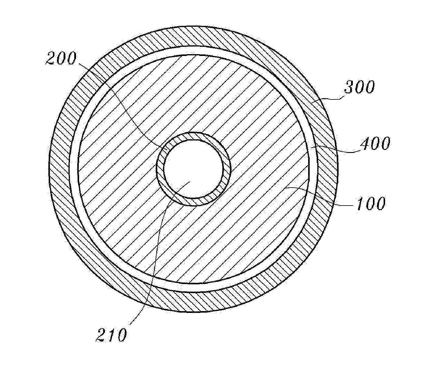
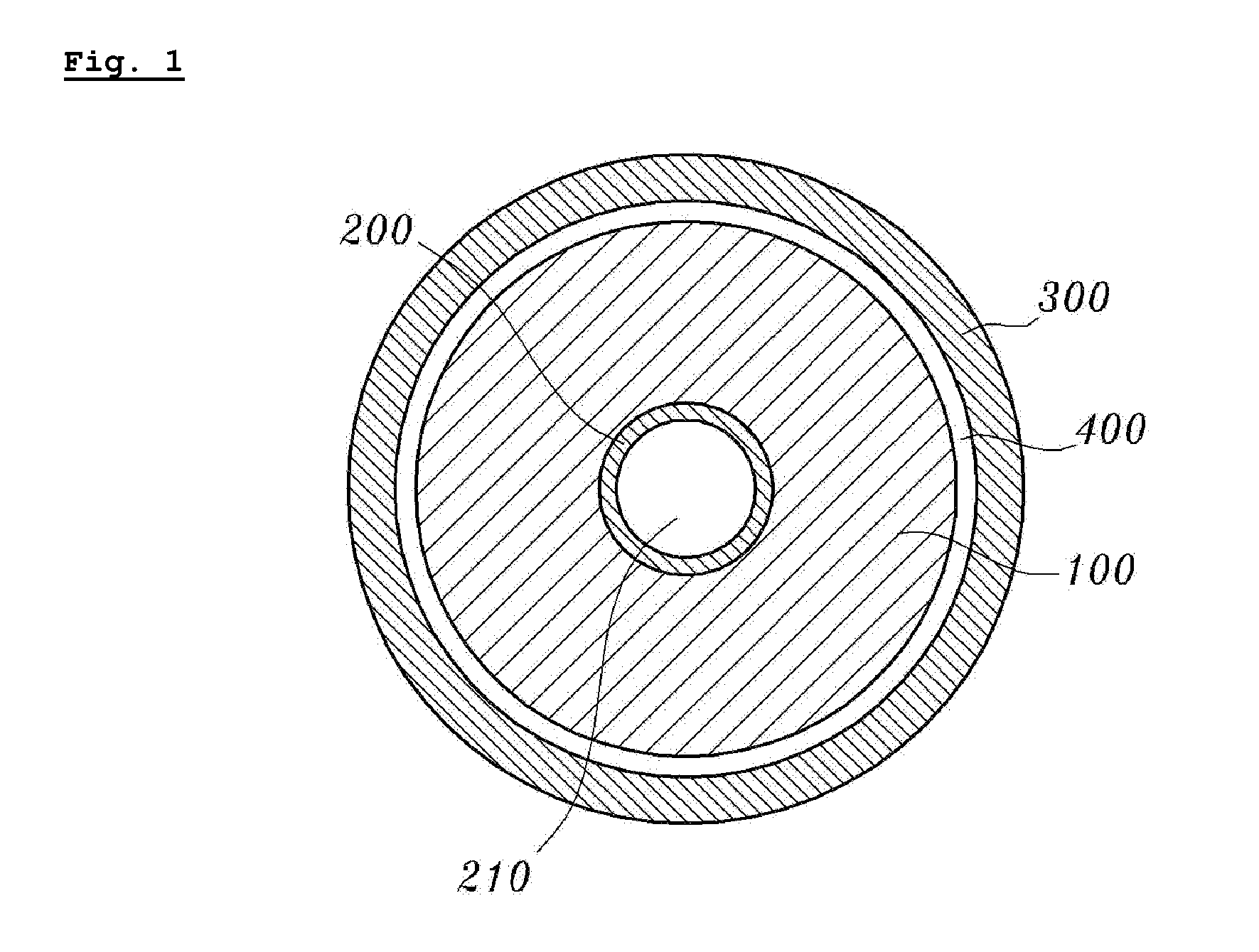
[0043]FIG. 1 illustrates a constitution of a nuclear fuel rod for a fast reactor according to an embodiment.

[0044]Referring to FIG. 1, the nuclear fuel rod for a fast reactor according to an embodiment may include a tubular fuel materials 100, a tubular inner pipe 200, a tubular cladding pipe 300 and a liquid metal 400 (or He gas or vacuum depe...


PUM


Abstract

A nuclear fuel rod for a fast reactor includes tubular fuel materials comprising a hollow portion formed therein, a tubular inner pipe inserted into the hollow portion of the tubular fuel materials to prevent collapse of the tubular fuel materials due to combustion of nuclear fuel, a tubular cladding pipe which surrounds the tubular fuel materials, and a liquid metal, or He gas or vacuum applied in a gap between the tubular fuel materials and the tubular cladding pipe.

Description

CROSS-REFERENCES TO RELATED APPLICATION[0001]This application claims priority from Korean Patent Application No. 10-2011-0141175, filed on Dec. 23, 2011, in the Korean Intellectual Property Office, the contents of which are incorporated herein by reference in its entirety.BACKGROUND OF THE INVENTION[0002]1. Field of the Invention[0003]The present invention relates to a nuclear fuel rod for a fast reactor, and more particularly, to a nuclear fuel rod for a fast reactor in which a reactor core of a sodium-cooled fast reactor (SFR) is designed compact-sized.[0004]2. Description of the Related Art[0005]The fast reactor is generally known for pyroprocessing in which nuclear waste from the light water reactor is recycled.[0006]The fast reactor, and more specifically, the sodium-cooled fast reactor (SFR) continuously breeds more fuel for fission in the reactor than it consumes. Further, the nuclear waste from the light water reactors has relatively long half life and nucleus with high radi...

Claims


Application Information

Patent Timeline
IPC IPC(8): G21C3/16
CPCG21C3/16G21C3/20G21C3/07Y02E30/40Y02E30/30G21C3/17
Inventor BAEK, JONG-HYUKLEE, CHAN-BOCKKIM, JUN-HWANCHEON, JIN-SIKLEE, BYOUNG-OON
Owner KOREA ATOMIC ENERGY RES INST
Learn More