
Fan motor

a technology of fan motor and fan body, which is applied in the direction of piston pumps, dynamo-electric machines, fluid engines, etc., can solve the problems of reducing the performance imposing large constraints on the attachment reducing the air volume of the fan motor, so as to reduce the amount of resin materials used

Active Publication Date: 2013-07-04
NIDEC CORP
View PDF5 Cites 8 Cited by
  • Summary
  • Abstract
  • Description
  • Claims
  • Application Information

AI Technical Summary

Benefits of technology

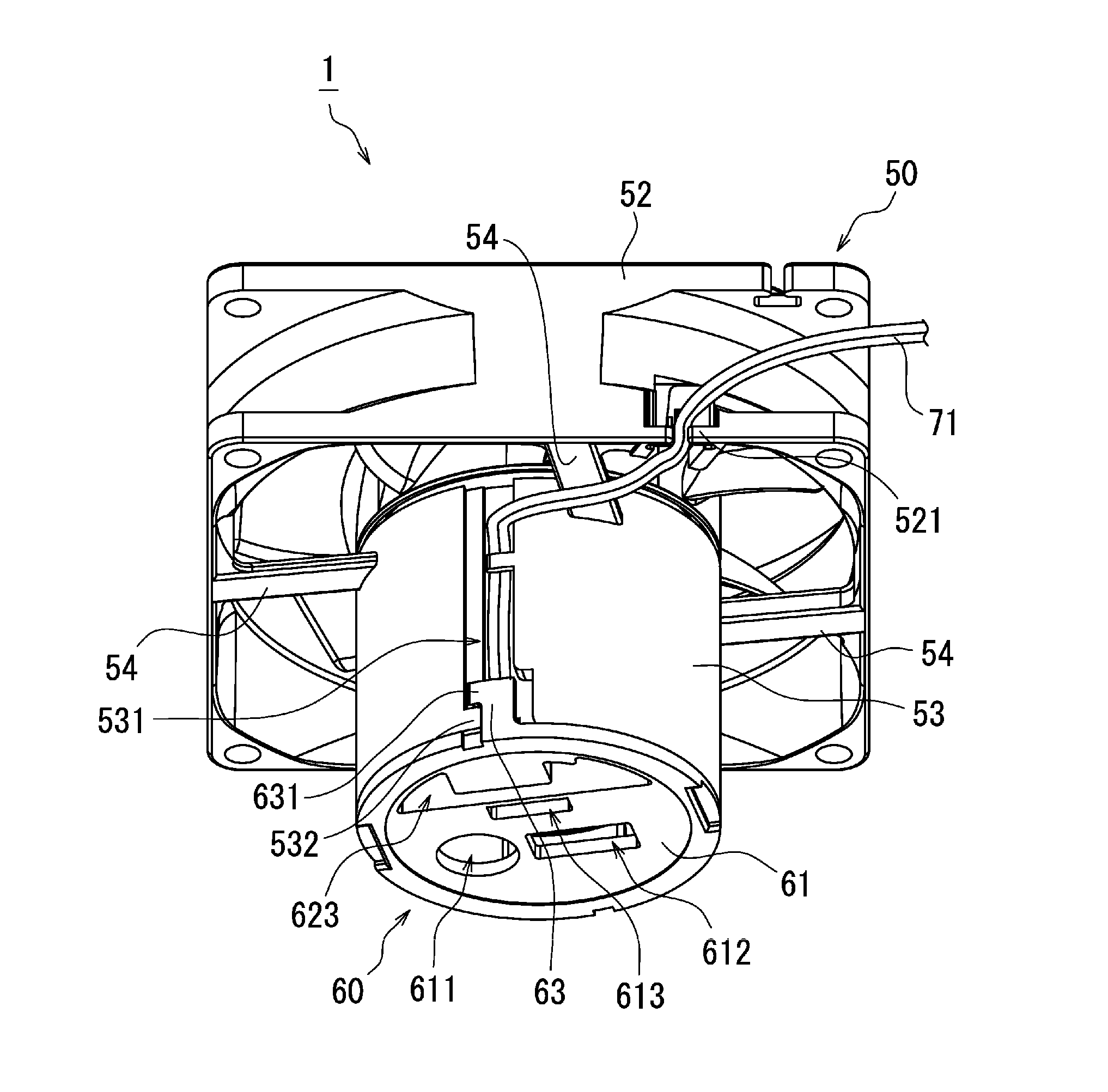
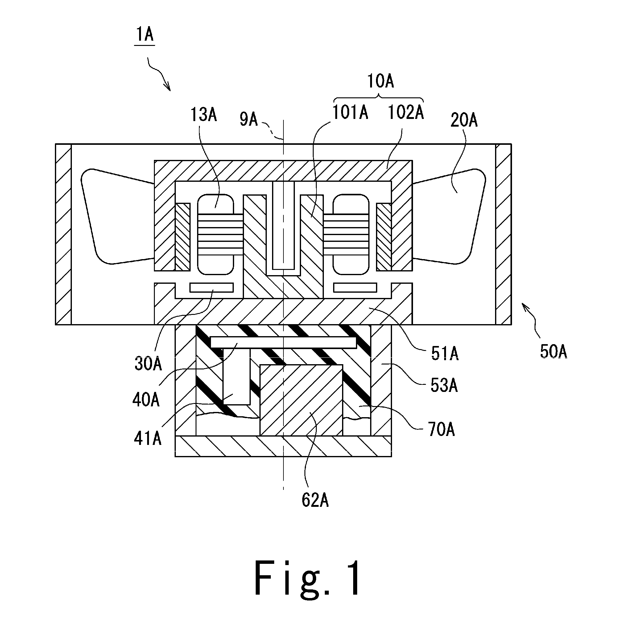
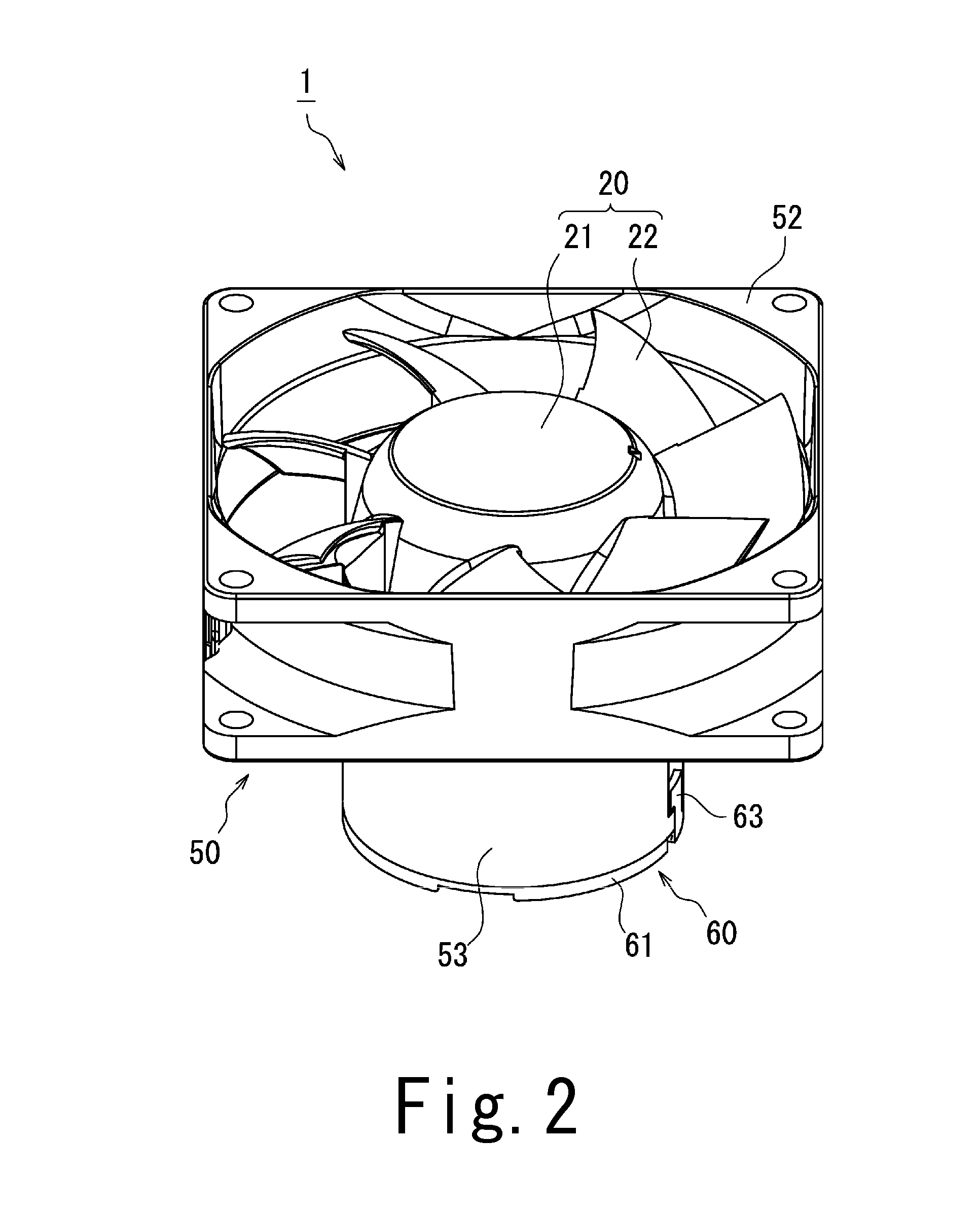
This patent describes a fan motor that includes a motor, an impeller, a control board, an AC / DC converter board, and electronic components mounted on the control board. The motor, impeller, and control board are all housed in a base portion, while the AC / DC converter board is located in a case portion that extends from the base portion. The interior of the case portion is filled with resin material. The technical effect of this design is the ability of the fan to create an air current and to convert alternating current to direct current. Electronic components are protected from water droplets and the amount of resin material used is reduced.

Problems solved by technology

However, an AC / DC converter is required to drive the DC motor in an environment where only an AC power supply is available.
This leads to a decrease in the air volume of the fan motor.
This structure imposes great constraints on attachment of the fan motor to a target device.
An increased size of the bearing boss restricts the size of a stator and that of blades, and this leads to a decrease in performance of the fan motor.
However, in the case where a large electronic component is mounted on a portion of the AC / DC converter board, it is difficult to cover this electronic component and an adjacent area, and a remaining portion of the AC / DC converter board, with a small amount of the resin material.

Method used


Image

  • Fan motor
  • Fan motor
  • Fan motor

Examples


Embodiment Construction

[0019]Hereinafter, preferred embodiments of the present invention will be described with reference to the accompanying drawings. It is assumed herein that a direction parallel or substantially parallel to a central axis of a fan motor is referred to by the term “axial direction”, “axial”, or “axially”, that directions perpendicular or substantially perpendicular to the central axis of the fan motor are referred to by the term “radial direction”, “radial”, or “radially”, and that a direction along a circular arc centered on the central axis of the fan motor is referred to by the term “circumferential direction”, “circumferential”, or “circumferentially”. It is also assumed herein that a vertical direction is the axial direction, and that a side on which a base portion is arranged with respect to a case portion is defined as an upper side. The shape of each member or portion and relative positions of different members or portions will be described based on the above assumptions. It sh...


PUM


Abstract

A fan motor includes a motor; an impeller; a motor control board; an AC / DC converter board; electronic components mounted on the AC / DC converter board; and a housing arranged to contain the motor, the impeller, the motor control board, and the AC / DC converter board. The housing includes a base portion arranged to hold a stationary portion of the motor on an axially upper side thereof; and a case portion arranged to extend to assume a tubular shape on an axially lower side of the base portion. The AC / DC converter board is arranged in an interior space of the case portion. At least a portion of the interior space is filled with a resin material. Surfaces of the AC / DC converter board and the electronic components are covered with the resin material. The fan motor further includes a projecting portion arranged to project into the interior space.

Description

BACKGROUND OF THE INVENTION[0001]1. Field of the Invention[0002]The present invention relates to a fan motor.[0003]2. Description of the Related Art[0004]Axial fan motors arranged to produce axial air currents by rotating impellers using driving forces of motors are known. The axial fan motors are installed, for example, in household electrical appliances, office automation appliances, transportation equipment, and so on, and are used for the purposes of dispersing heat from electronic components, circulating internal gases, and so on. The structures of such known fan motors are described, for example, in JP-UM-A 04-097496 and WO 2003 / 015243.[0005]Recent years have seen an increasing demand to use DC motors instead of AC motors in order to improve the efficiency of fan motors. However, an AC / DC converter is required to drive the DC motor in an environment where only an AC power supply is available. Moreover, when an AC / DC converter board is arranged in a wind channel in the fan moto...

Claims


Application Information

Patent Timeline
Patent Type & Authority Applications(United States)
IPC IPC(8): F04D25/06
CPCF04D25/06F04D25/0646F04D25/068H02K9/04H02K9/06
Inventor OGUMA, YOSHIAKIHIRAKI, MASAMUNEHAYASHIDA, RYOTAKOBAYASHI, MAKOTOHAMANO, SHINSUKE
Owner NIDEC CORP
Learn More