This helps you quickly interpret patents by identifying the three key elements:
Problems solved by technology
Method used
Benefits of technology
Benefits of technology
The present invention is about a rotary dryer that saves energy by reducing heating and power needed for rotation. It achieves this by reducing contact between heating tubes and the material to be dried, and by increasing the hold up ratio.
Problems solved by technology
Accordingly, in the conventional apparatus, heating tubes are not arranged in the vicinity of the shaft center of the rotating shell, thereby resulting in being inefficient and non-economical.
However, this case results in causing a power increase for lifting the material to be dried within the rotating shell.
Accordingly, the above has been also non-economical with low energy efficiency.
Method used
Image
Click on the blue label to locate the original text in one second.
Reading with bidirectional positioning of images and text.
Examples
examples
[0086]Next, following is description of a comparison test between an example based on the above embodiment and a conventional example performed by using a batch testing machine of an indirectly heating rotary dryer.
[0087]First, specifications of the batch testing machine of an indirectly heating rotary dryer are as indicated below.
[0098]FIG. 9 is a graph indicating the results of capability of dryingmoisture in the material to be dried with the example a...
example
[0117]Supplying amount of material to be dried: 470 kg / h
[0118]Inlet moisture content: 33.1%
[0119]Outlet moisture content: 9.8%
[0120]STD idle operation power: 3.11 kW
[0121]STD drive power: 3.22 kW
[0122]Power increase due to load operation: 0.11 kW
[0123]The hold up ratio was calculated on collecting the total amount of the dried material in the indirectly heating rotary dryer after the drying test was completed. The hold up ratio was 57%.
PUM
Abstract
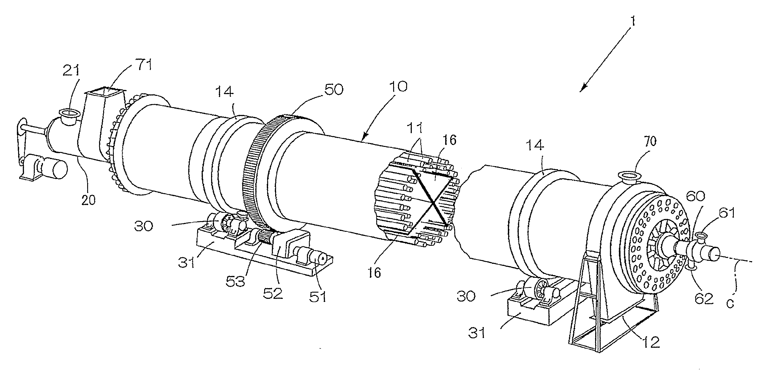
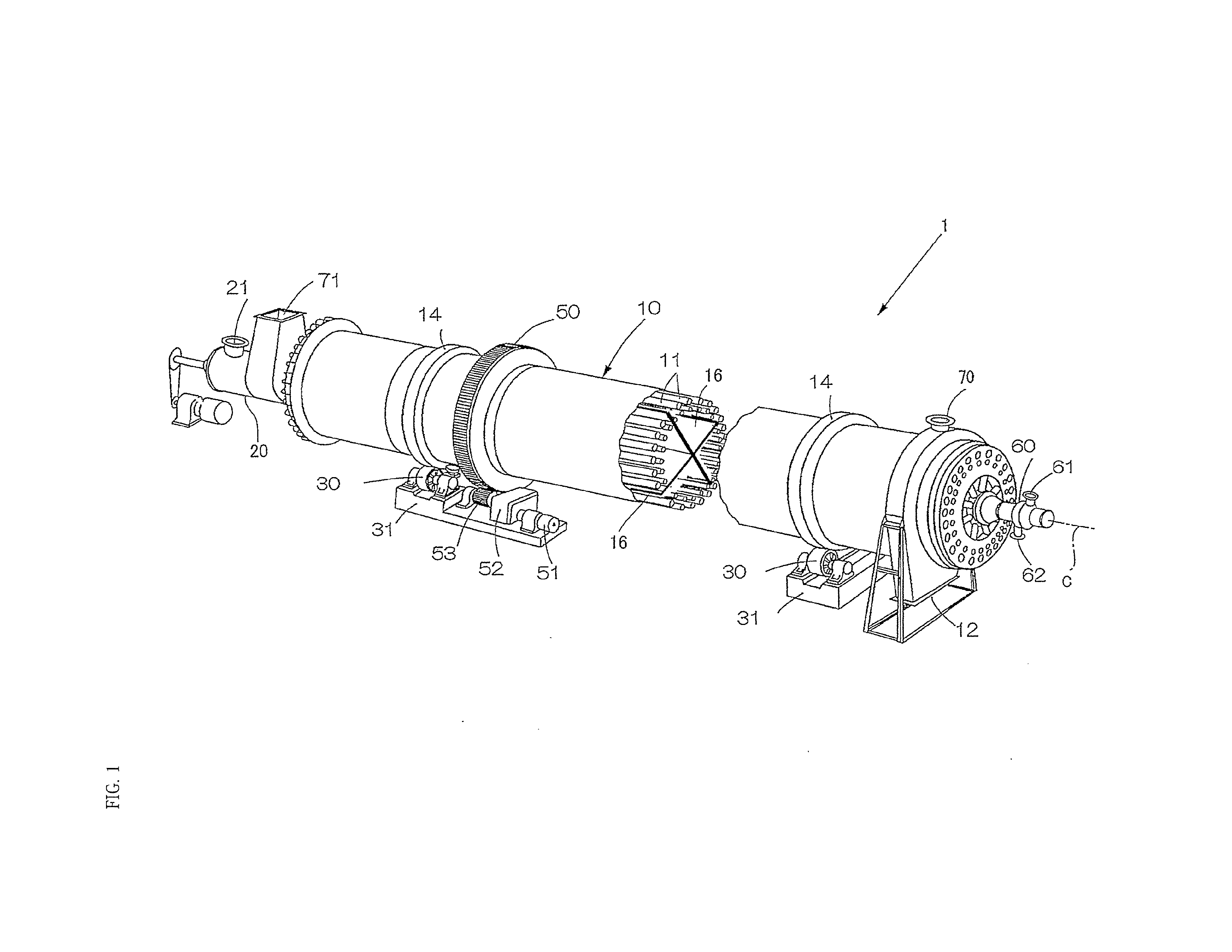
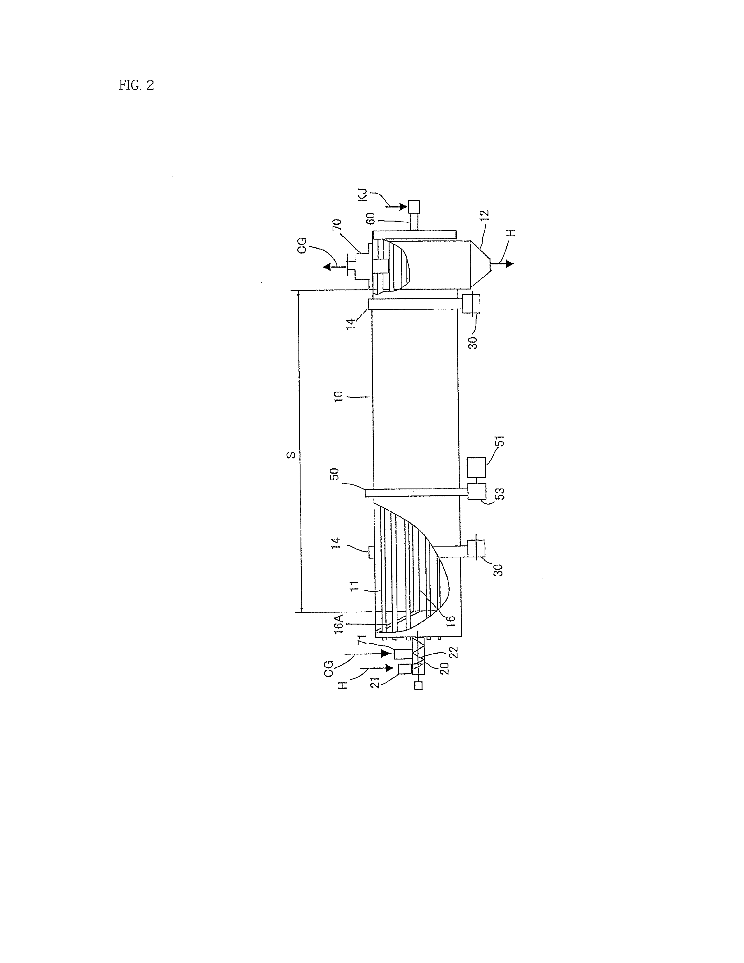
Provided is an indirectly heating rotary dryer which has achieved enhanced energy-saving performance by reducing heating tubes non-contacting with material to be dried and reducing power required for rotation even when a hold up ratio is increased.Specifically provided is an indirectly heating rotary dryer having four partition walls extended respectively along a shaft center in an inner space of a rotating shell at angle intervals of 90 degrees in the vertical and horizontal directions. The four partition walls partition the inner space of the rotating shell at a lateral section of the rotating shell into four approximately-sector-shaped small spaces respectively extended along the shaft center. Heating tubes are aligned in the rotating shell in three lines extended respectively in parallel to the shaft center of the rotating shell. The heat tubes heat and dry the material to be dried by supplying heated steam to the heating tubes and performing heat exchange with the material to be dried in the rotating shell.
Description
TECHNICAL FIELD[0001]The present invention relates to an indirectly heating rotary dryer, which has achieved enhanced energy saving performance by reducing heating tubes non-contacting with material to be dried and reducing power required for rotation even when a hold up ratio is increased. The invention can be applied especially to an apparatus to dry or cool materials to be processed.BACKGROUND ART[0002]A steam tube dryer (hereinafter, appropriately called STD as well) being an indirectly heating rotary dryer is provided with a rotating shell of which length is 10 to 30 meters. Drying is performed in the rotating shell with heated steam as external heat for drying during a course where material to be dried, fed from one end side of the rotating shell is discharged from the other end side while the rotating shell is rotated.[0003]Specifically, wet powders or granular powders being material to be dried are dried as being contacted to heated tubes in which steam and the like is fed a...
Claims
Application Information
Patent Timeline
Application Date:The date an application was filed.
Publication Date:The date a patent or application was officially published.
First Publication Date:The earliest publication date of a patent with the same application number.
Issue Date:Publication date of the patent grant document.
PCT Entry Date:The Entry date of PCT National Phase.
Estimated Expiry Date:The statutory expiry date of a patent right according to the Patent Law, and it is the longest term of protection that the patent right can achieve without the termination of the patent right due to other reasons(Term extension factor has been taken into account ).
Invalid Date:Actual expiry date is based on effective date or publication date of legal transaction data of invalid patent.

