Grid forming machine for making plates of electric storage cells

a technology of electric storage cells and forming machines, which is applied in the direction of stock shearing machines, final product manufacturing, manufacturing tools, etc., can solve the problems of not being able to produce grids with a high quality standard, the lead band of these machines is not high productivity, and the band is obviously limited, so as to achieve high production of grids per hour and continuous punching lead bands.

Active Publication Date: 2013-07-11
SOVEMA
View PDF7 Cites 3 Cited by
  • Summary
  • Abstract
  • Description
  • Claims
  • Application Information

AI Technical Summary

Benefits of technology

[0037]Thanks to this machine, it is possible to continuously punch lead bands extremely quickly, allowing a high production of grids per hour.
[0038]Moreover, such a machine is at the same time constructively simple and operatively totally reliable.

Problems solved by technology

One drawback is the fact that the supply in steps of the lead band of these machines does not make it possible to achieve high productivity due to the fact that the speed of forward movement of the band is obviously limited by the limits of mechanical resistance of the lead, which, during the continuous accelerations and decelerations, could stretch and deform.
A further drawback derives from the fact that these machines do not allow the production of grids with a high quality standard.
The forward movement in sections of the band also does not allow high productivity of the grid forming machine.
The aforementioned type of machines for continuously producing grids for electric storage cells, whilst therefore representing progress with respect to the machines advancing in steps quoted earlier, has demonstrated a not yet entirely satisfactory efficiency, allowing the production of a still too small number of grids per hour.
Indeed, with respect to the entire stroke carried out by the press moved by the eccentric, the useful section to cut the band having the middle horizontal component equal to the speed of forward movement of the band, is very short.
Even if the vertical incision component is very small, the press, having to follow the entire journey of the eccentric, must follow a very long stroke, thus with lots of friction and with the consequent need to carry out its cooling with a suitable system.
A further drawback is the fact that to keep the horizontal component of the speed of the press substantially equal to the speed of forward movement of the band, the trajectory of the stroke of the press is quite flat in the incision step, thus with a fairly modest vertical speed component of the press for the incision of the band.
This circumstance usually leads to the constructive difficulty of having to necessarily foresee the movement of the piece-remover as well as of having to provide stopping means of the piece-remover itself, which of course cannot abut with force against the lead band.
Indeed, the horizontal deceleration of the press after incision can, coinciding with substantial expansions of the band, lead to the failed detachment of the lead from the teeth of the press.
This circumstance actually limits the operation of this known type of machine to expansions of a modest size.
A further drawback of this last type of machine is that it does not make it possible to simply and cost-effectively vary the thickness of the band to be pressed, or the type of expansion to be carried out and therefore, overall, the shape of the continuous grid that it is wished to obtain.
Such a machine for the continuous production of lead grids allows substantial production speeds to be reached, but it has the main drawback of not allowing, during the solidification of the lead alloy, the formation of an optimal crystalline structure, i.e. one that is spherical, substantially without dendritic formations and with uniformly distributed grains.
Such a machine is, for example, described in U.S. Pat. No. 6,944,942 and WO 2005087454, and in practice it has proven to be incapable of satisfactorily solving both the problem of the extraction of the scrap from the recesses, and the problem of the separation of the grid from the matrix roller carrying the recesses on which it has come to be formed.
Moreover, the grids obtained with this technology are of very poor quality and with the threads of the meshes having a quite irregular shape.
The known machines considered above that foresee the formation of the grid through the expansion of a lead band do not allow a high quality to be achieved, like that which can be more easily ensured by the formation of the grid through punching of the lead band.

Method used


Image

  • Grid forming machine for making plates of electric storage cells
  • Grid forming machine for making plates of electric storage cells
  • Grid forming machine for making plates of electric storage cells

Examples


Embodiment Construction

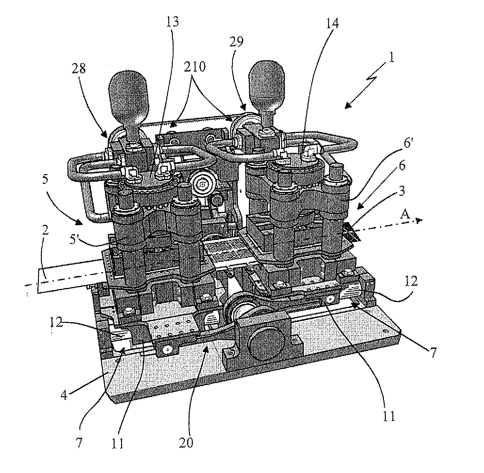
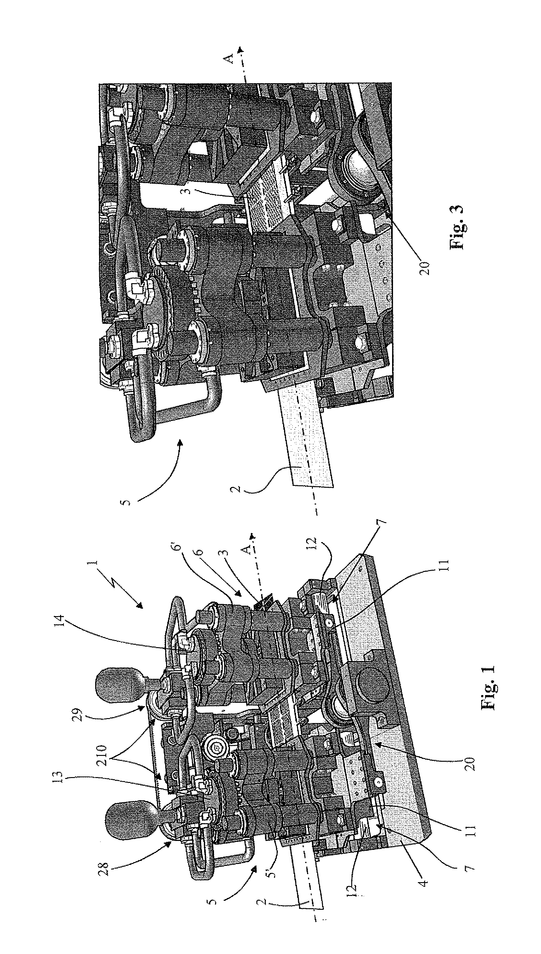
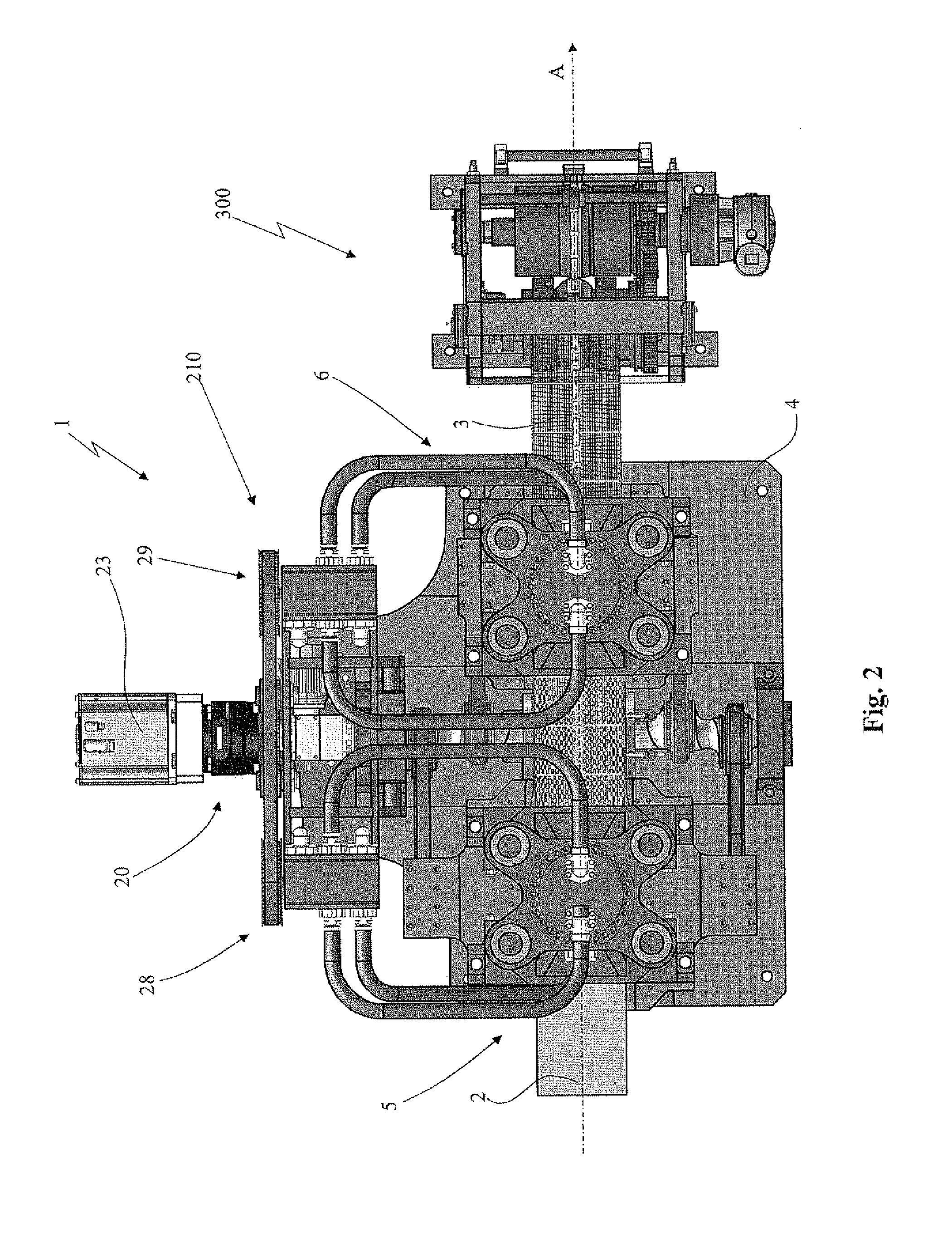
[0052]With reference to the attached drawings, the grid forming machine for making plates of electric storage cells object of the present invention has been wholly indicated with 1. It is operatively supplied continuously and at constant speed with a continuous lead band 2, advantageously obtained in one same production line, through a melting unit for continuously forming the lead band, arranged upstream of the grid forming machine 1. The machine 1 object of the present invention in output produces a continuous lead grid 3, which is treated through a traction group, a levelling group and a lug shearing group (not illustrated in the attached figures because they are of the per se known type), for example foreseen on a single machine arranged downstream of the machine in object and in the same production line.

[0053]The scrap produced by the grid forming machine 1, as well as that produced by the lug shearing machine, can advantageously be sent directly to the lead melting unit allowi...


PUM

PropertyMeasurementUnit
speedaaaaaaaaaa
areaaaaaaaaaaa
shapeaaaaaaaaaa

Abstract

Grid forming machine for making plates of electric storage cells, which comprises two pressing towers operatively active in succession on a continuous lead band that advances with a substantially constant speed, and each equipped with a framework slidably mounted along the direction of forward movement of the band on the support structure of the machine; with a linear actuator mounted on the framework of the tower and supporting a relative press; and with, a matrix fixed to the framework under the linear actuator. The two presses of the two pressing towers are moved cyclically and alternatingly by the linear actuators to move between a raised position and a lowered position, in which they cut the band forming it in the shape of a continuous grid. Moving means are foreseen acting on the pressing towers to move them sliding with a back-and-forth cyclical stroke equipped with at least one operative section with substantially the same speed as that of forward movement of the continuous band, and actuation means to cyclically and alternatingly control the two linear actuators to move the presses from the raised position to the lowered position at the operative section of the cyclical stroke of the corresponding pressing towers.

Description

FIELD OF APPLICATION[0001]The present invention concerns a grid forming machine for making plates of electric storage cells, according to the preamble of the independent claim.[0002]The machine concerned is intended to be advantageously used in production processes of electric storage cells in which, starting from a continuous lead band, a continuous grid is obtained that, when cut into pieces of predetermined length, makes it possible to make the single plates for inserting into the electric storage cells, through successive steps, like for example spreading with a lead oxide-based paste.STATE OF THE ART[0003]Currently, on the market, machines for forming grids made from lead are common in which it is foreseen to advance a continuous band in successive steps between a press and a matrix where, through punching in succession, the incision and the expansion of the band and the consequent forming of the mesh of the grids takes place.[0004]Machines of this type are described for exampl...

Claims


Application Information

Patent Timeline
Patent Type & Authority Applications(United States)
IPC IPC(8): B23D25/04
CPCB23D25/04B21D31/043H01M4/73H01M4/74H01M4/82Y02E60/10Y10T83/4757Y02P70/50B21D31/04H01M10/058
Inventor FARINA, PIETRO
Owner SOVEMA
Why Eureka
Try Eureka